NEC uPD780328 Subseries User Manual
Page 30
CHAPTER 3 INSTALLATION
User’s Manual U16214EJ1V0UM
30
<3> Make sure that the parts board (X2) is wired as shown in Figure 3-13.
<4> Remove the parts board that is mounted in the IE-780338-NS-EM1’s X2 socket.
<5> Connect the parts board from <2> above to the socket from which the parts board was removed (from
<4> above). Check the pin 1 mark to make sure the board is mounted in the correct direction.
<6> Connect the IE-780338-NS-EM1 to the IE-78K0-NS or IE-78K0-NS-A.
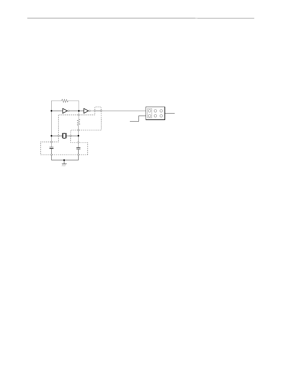
The above steps configure the following circuit and enable supply of the clock from the mounted resonator
to the emulation device.
Remarks 1. The sections enclosed in broken lines indicate parts that are attached to the parts board.
2. There is JP8 on the IE-78K0-NS or IE-78K0-NS-A.
10 M
Ω
HCU04
HCU04
9 8
5
Rx
10
11
4
13
CA
2
3
CB
12
IE-78K0-NS or IE-78K0-NS-A side
(Emulation device)
Target
system
1 3
5
2 4
6
JP8