2 clock settings, 1 overview of clock settings – NEC uPD780328 Subseries User Manual
Page 20
CHAPTER 3 INSTALLATION
User’s Manual U16214EJ1V0UM
20
3.2
Clock Settings
3.2.1 Overview of clock settings
The main system and subsystem clocks to be used during debugging can be selected from (1) to (3) below.
(1) Clock that is already mounted on emulation board
(2) Clock that is mounted by user
(3) External
clock
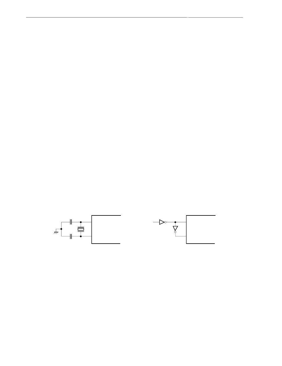
If the target system includes an internal clock, select either (1) Clock that is already mounted on emulation
board or (2) Clock that is mounted by user. For an internal clock, a resonator is connected to the target device
and the target device’s internal oscillator is used. An example of the external circuit is shown in part (a) of Figure 3-4.
During emulation, the resonator that is mounted on the target system is not used. Instead, the clock that is mounted
on the emulation board connected to the IE-78K0-NS or IE-78K0-NS-A is used.
If the target system includes an external clock, select (3) External clock.
For an external clock, a clock signal is supplied from outside the target device and the target device’s internal
oscillator is not used. An example of the external circuit is shown in part (b) of Figure 3-4.
Caution
The IE system will be hung-up if the main system clock is not supplied normally. Moreover, be
sure to input a rectangular wave as the clock from the target. The IE system does not operate if
the crystal resonator is directly connected to X1 (main system clock) and XT1 (subsystem
clock).
Figure 3-4. External Circuits Used as System Clock Oscillator
(a) Internal clock
(b) External clock
X2 or XT2
X2 or XT2
Target device
Target device
External
clock
X1 or XT1
X1 or XT1