Mode 2 bidirectional timing, Figure 4-40. mode 2 bidirectional timing, Mode 2 bidirectional timing -54 – National Instruments AT E Series User Manual
Page 101
Chapter 4
Connecting Signals
4-54
ni.com
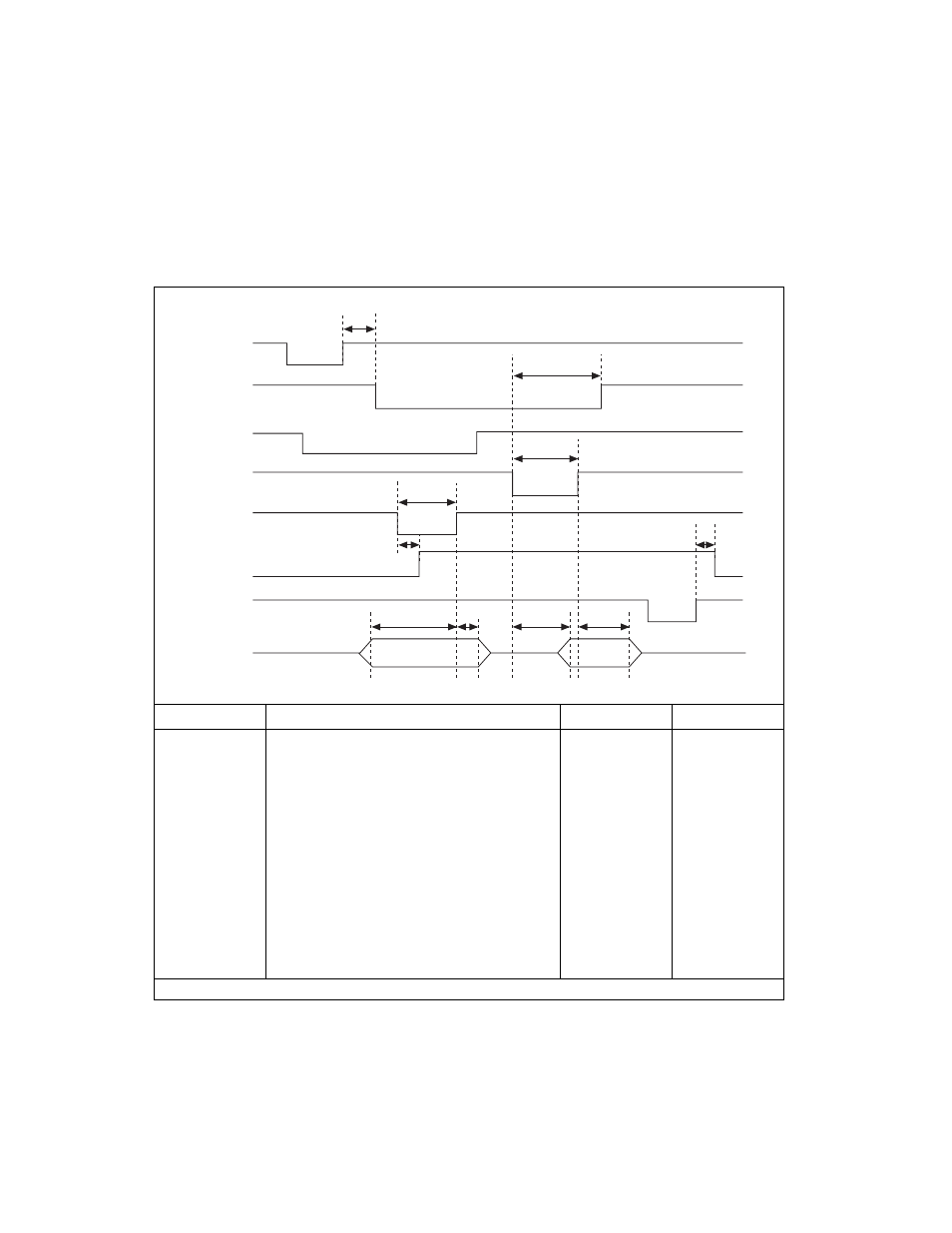
Mode 2 Bidirectional Timing
Figure 4-40 details the timing specifications for bidirectional transfers in
Mode 2.
Figure 4-40. Mode 2 Bidirectional Timing
Name
Description
Minimum
Maximum
T1
WR* = 1 to OBF* = 0
—
150
T2
Data before STB* = 1
20
—
T3
STB* Pulse Width
100
—
T4
STB* = 0 to IBF = 1
—
150
T5
Data after STB* = 1
50
—
T6
ACK* = 0 to OBF = 1
—
150
T7
ACK* Pulse Width
100
—
T8
ACK* = 0 to Output
—
150
T9
ACK* = 1 to Output Float
20
250
T10
RD* = 1 to IBF = 0
—
150
All timing values are in nanoseconds.
T1
T6
T7
T3
T4
T10
T2
T5
T8
T9
WR *
OBF *
INTR
ACK *
STB *
IBF
RD *
DATA
See also other documents in the category National Instruments Hardware:
- Instrument Driver NI-DMM (12 pages)
- 24-Bit Half/Full-Bridge Analog Input Module NI 9237 (36 pages)
- NI PXIe-8105 (76 pages)
- PXI NI 5401 (60 pages)
- Fieldpoint CFP-2210 (38 pages)
- NI 781xR (48 pages)
- NI 6233 (180 pages)
- 6508 PCI-DIO-96 (93 pages)
- PXI/CompactPCI Embedded Computer NI PXI-8108 (83 pages)
- NI 9233 (34 pages)
- NI USB-9219 (25 pages)
- GPIB-PC (262 pages)
- cFP-RTD-122 (15 pages)
- USB device 625x (23 pages)
- Isolated Analog Input Modules SCC-AI01 (18 pages)
- NI PCI-6111 (118 pages)
- NI USB-6008 (32 pages)
- PC-DIO-24 (75 pages)
- NI 9474 (31 pages)
- NI 6013 (109 pages)
- PXI-1428 (46 pages)
- NI PCI-5911 (51 pages)
- 2 SD Card Memory Module NI 9802 (16 pages)
- cFP-20xx (24 pages)
- NI USB-9234 (23 pages)
- NI 9871 (24 pages)
- Interface Device NI PCI-1426 (35 pages)
- 9211A (19 pages)
- Module NI PXI-8250 (39 pages)
- 8330 Series (30 pages)
- NI PXIe-8360 (40 pages)
- Deterministic Ethernet Expansion Chassis NI 9144 (65 pages)
- NI 6509 (23 pages)
- NI MATRIXx Xmath (127 pages)
- NI 9481 (23 pages)
- Monochrome Image Acquisition Device NI 1410 (34 pages)
- VXI-1394 (74 pages)
- NI PXI-8104 (69 pages)
- NI 9235 (38 pages)
- 370620B-01 (17 pages)
- FP-RTD-124 (15 pages)
- VXI-USB (61 pages)
- NI PCI-8254R (45 pages)
- Interface Device NI PCI-8254R (16 pages)