Figure 2-26. scxi-1127/1128 relay configuration, Figure 2-26, Scxi-1127/1128 relay configuration -30 – National Instruments SCXI-1127 User Manual
Page 65: Front signal connector
Chapter 2
Using the SCXI-1127/1128
2-30
ni.com
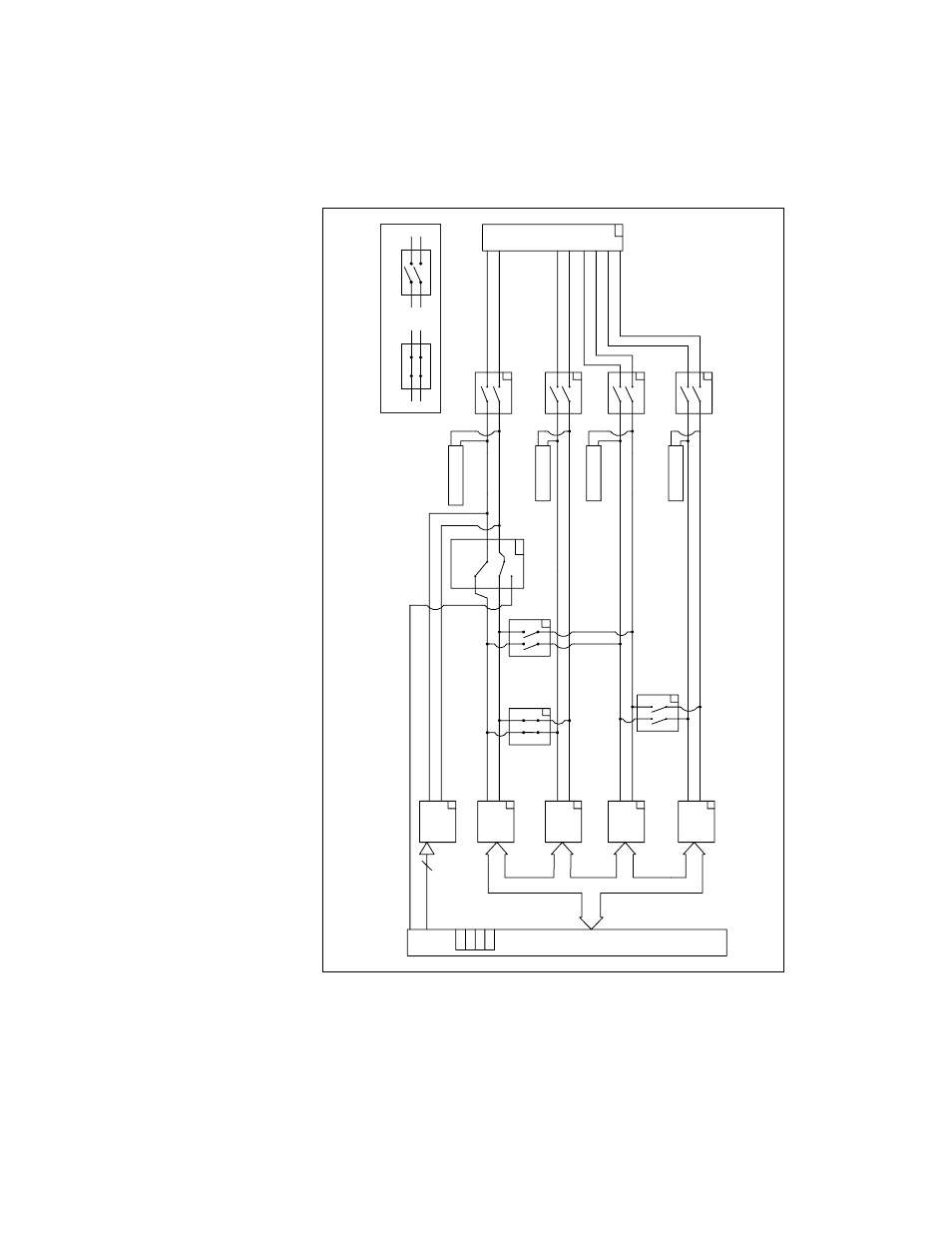
Figure 2-26. SCXI-1127/1128 Relay Configuration
CJS Relay
Relay
Channel Bank 1
Relay
Channel Bank 2
Relay
Channel Bank 3
Relay
Channel Bank 4
High-voltage Rear Signal Connector
CH+ (24:31)
CH
–
(24:31)
CH+ (16:23)
CH
–
(16:23)
CH+ (8:15)
CH
–
(8:15)
CH+ (0:31)
CH
–
(0:31)
CH+ (0:7)
CH
–
(0:7)
9
5
2
8
9
9
9
+
–
9
9
9
9
9
9
6
7
AISENSE
CJTEMP+, CJTEMP
–
COM3
–
COM3+
COM2
–
COM2+
COM1
–
COM1+
COM0
–
COM0+
HVAB3
–
HVAB3+
HVAB2
–
HVAB2+
HVAB1
–
HVAB1+
HVAB0
–
HVAB0+
AISENSE
OUT0 Return to
Front Connector
OUT1 Return to
Front Connector
OUT2 Return to
Front Connector
OUT3 Return to
Front Connector
OUT0
OUT1
OUT2
OUT3
Front Signal Connector
Closed Switch
Open Switch
CH0+/
–
–
CH7+/
–
CH8+/
–
–
CH15+/
–
CH16+/
–
–
CH23+/
–
CH24+/
–
–
CH31+/
–
BC01
BC02
BC23
AB0
AB1
AB2
AB3
One-WIRE
This manual is related to the following products: