Figure 2-3. 2-wire wiring diagram, Figure 2-3, Wire wiring diagram -4 – National Instruments SCXI-1127 User Manual
Page 39
Chapter 2
Using the SCXI-1127/1128
2-4
ni.com
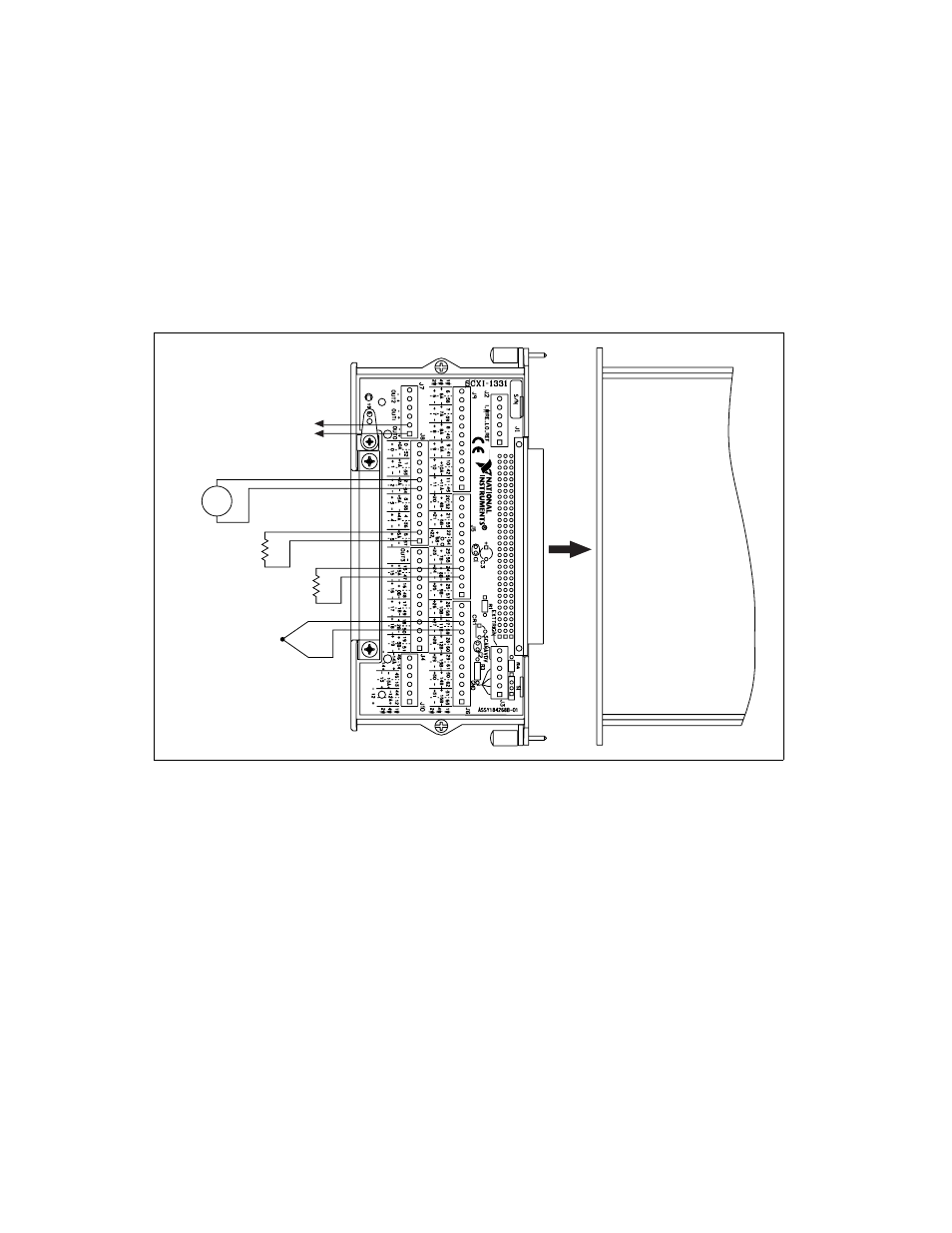
Figure 2-3 shows an example of a 2-wire configuration using the
SCXI-1331 terminal block. The diagram shows the 2-wire terminal block
connections for channels 2, 5, 24, and 27. Channel 2 measures a voltage
source (V
1
). The positive terminal of channel 2 is labeled +2 with the
negative channel labeled –2. The output of the multiplexer is available
through the OUT0 bus.
Figure 2-3. 2-Wire Wiring Diagram
You can connect different types of 2-wire inputs to the SCXI-1127. For
example, in Figure 2-3, a thermocouple (V
2
) is shown connected to
channel 27, and on channel 5 (R
1
) and 24 (R
2
) resistance measurements are
being made. Consult the
Making Temperature Measurements
section for
more information on temperature compensation measurements for making
accurate thermocouple measurements.
SCXI-1127
R
1
R
2
V
2
Thermocouple
Multiplexer Output
–
+
V
1
–
+
OUT0±