Figure 2-24. 8 x 16 matrix parts locator diagram, Figure 2-24, 16 matrix parts locator diagram -27 – National Instruments SCXI-1127 User Manual
Page 62
Chapter 2
Using the SCXI-1127/1128
© National Instruments Corporation
2-27
2.
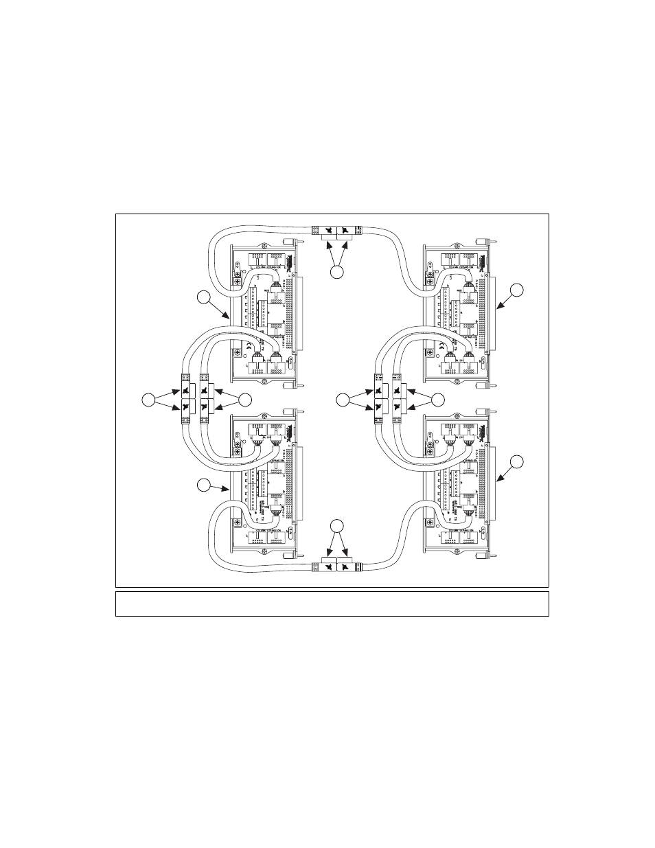
Expand the rows to the target number, 8 in this case, by connecting the
columns of the appropriate number of 4
× 16 matrix blocks, two in this
case, using matrix expansion cables.
Figure 2-24 shows four SCXI-1332s connected to form a 8
× 16 matrix.
Figure 2-24. 8
×
16 Matrix Parts Locator Diagram
1
Matrix Expansion Cables
2
SCXI-1127/1332 #3
3
SCXI-1127/1332 #4
4
SCXI-1127/1332 #2
5
SCXI-1127/1332 #1
2
5
4
3
1
1
1
1
1
1
This manual is related to the following products: