Figure 2-1. scxi-1331 signal connections, Figure 2-1, Scxi-1331 signal connections -2 – National Instruments SCXI-1127 User Manual
Page 37
Chapter 2
Using the SCXI-1127/1128
2-2
ni.com
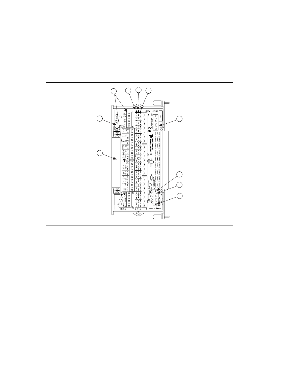
The SCXI-1331 terminal block consists of a shielded board with 84 screw
terminals for easy connection to the SCXI-1127/1128 input connector. The
SCXI-1331 is shown in Figure 2-1.
Figure 2-1. SCXI-1331 Signal Connections
Depending on the input mode configuration of the SCXI-1127/1128, the
SCXI-1331 has a maximum of 64, 1-wire channels; 32, 2-wire channels;
or 16, 4-wire channels. The SCXI-1331 also has terminals for external
triggering signals. The SCXI-1127/1128 supports the standard voltmeter
complete and scanner advanced triggering signals. The following sections
describe signal connections using the SCXI-1331 and the various input
mode configurations. For more information on scanning and triggering,
consult the
Hardware-Timed and Software Scanning
section.
1
Multiplexer Outputs
2
2-Wire Mode Channel Numbering
3
4-Wire Mode Channel Numbering
4
1-Wire Mode Channel Numbering
5
1-Wire Lo Reference (1_WIRE_LO_REF)
6
External Trigger Input (EXT_TRIG_IN)
7
Scanner Advanced Output (SCANADVD)
8
Ground Reference for Trigger Signals
9
Cable Strain Relief
10 Safety Ground Solder Lug
1
2
3
4
5
6
7
8
9
10