Figure 1-8 – National Instruments SCXI-1127 User Manual
Page 25
Chapter 1
Installing and Configuring the SCXI-1127/1128
© National Instruments Corporation
1-15
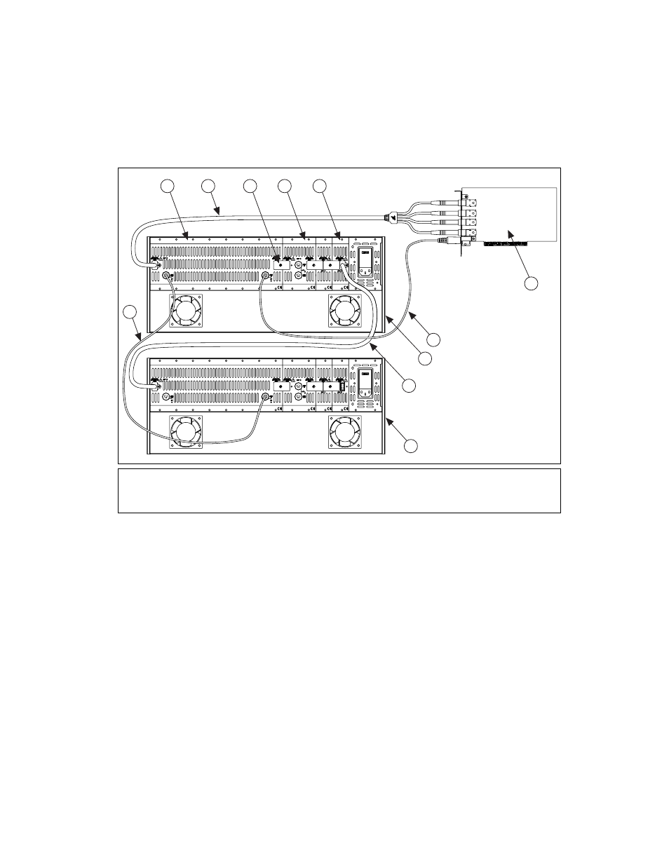
Refer to Figure 1-8 to set up this multichassis configuration.
Figure 1-8. 12-Slot to 12-Slot Multichassis Configuration Parts Locator Diagram
1.
Install the HVAB-backplane adapters and jumper blocks in the 12-slot
chassis as described in steps 1 through 3 in
2.
Connect the HV8-HV8 cable from the first chassis, normally the
connector behind slot 1, to the HVAB connector (behind slot 12) of the
next chassis.
3.
Connect the SH9MD-9MD cable from the AUX OUT connector of the
first chassis to the AUX IN connector (behind slot 5) of the next
chassis.
4.
Repeat steps 1 through 3 for each additional chassis.
1
8-Slot HVAB-Backplane Adapter
2
HV8-BAN4 Cable
3
8-Position HVAB Plug
4
2-Slot HVAB-Backplane Adapter
5
1-Slot HVAB-Backplane Adapter
6
NI 4060 for PCI
7
SH9MD-9MD Cable
8
12-Slot SCXI Chassis
9
HV8-HV8 Cable
10 12-Slot SCXI Chassis
11 SH9MD-9MD Cable
AB0+
AB0–
AB2+
AB2–
6
8
9
7
10
1
3
2
11
4
5