4 x 8 matrix configuration, Figure 2-18. 1 x 32 matrix wiring diagram, 8 matrix configuration -21 – National Instruments SCXI-1127 User Manual
Page 56: Figure 2-18, 32 matrix wiring diagram -21
Chapter 2
Using the SCXI-1127/1128
© National Instruments Corporation
2-21
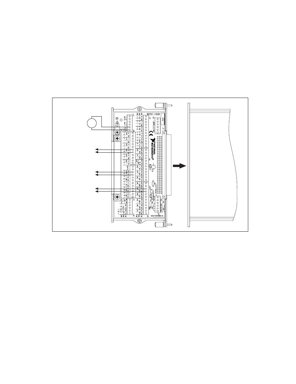
Figure 2-18 shows an example of the SCXI-1331 and SCXI-1127/1128
configured as a 1
× 32, 2-wire matrix. The diagram shows the 2-wire
terminal block connections for channels 3, 15, 27 and OUT0. You can use
this configuration to connect V
SOURCE
to one or all of the device under
test (DUT) channels.
Figure 2-18. 1
×
32 Matrix Wiring Diagram
4
ЧЧЧЧ 8 Matrix Configuration
You can configure the SCXI-1127/1128, with the SCXI-1332 as an 4
× 8,
four rows by eight columns, matrix. The SCXI-1332 terminal block has 12
pairs of screw terminals, eight pairs for accessing eight columns (C0...C7)
and four pairs for accessing four rows (R0...R3) of the 4
× 8 matrix when
installed in the front connector of the SCXI-1127/1128. In addition to the
screw terminals, the SCXI-1332 has six connectors for matrix expansion.
Four of the six connectors are for expanding the eight columns and the
other two connectors are for row expansion. The SCXI-1332 is shown in
Figure 2-19.
SCXI-1127
To Device Under
Test #1
–
+
–
+
To Device Under
Test #2
–
+
To Device Under
Test #3
V
SOURCE
–
+