Figure 2-19. scxi-1332 terminal block, Figure 2-19, Scxi-1332 terminal block -22 – National Instruments SCXI-1127 User Manual
Page 57
Chapter 2
Using the SCXI-1127/1128
2-22
ni.com
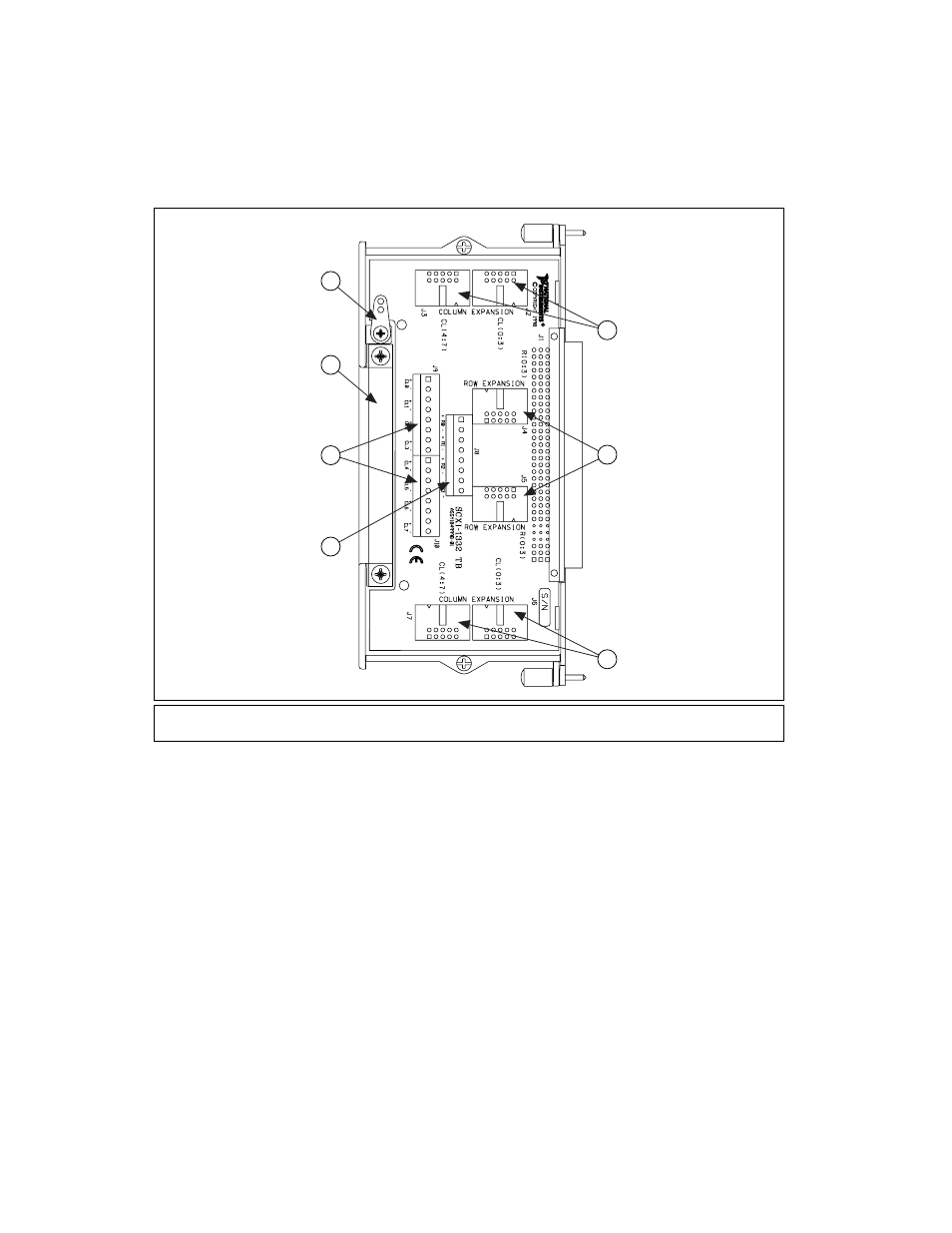
Figure 2-19. SCXI-1332 Terminal Block
The SCXI-1127/1128 installed with the SCXI-1332 provides you with an
4
× 8 matrix without any extra wiring except for hooking up your signals to
the columns and rows of the matrix. Refer to
for
information on using multiple SCXI-1127/SCXI-1332 systems to build
matrices larger than 4
× 8.
Figure 2-20 shows an example of an SCXI-1332 connected to an
SCXI-1127/1128. The SCXI-1127/1128 is configured for 4
× 8 matrix
operation by the software. This is an example of a power supply test station.
The purpose of this test station is to measure the output voltage of a power
supply under various load conditions. The loads are connected to the first
four columns, C0...C3. The power supply is connected to row 0 and is the
DUT. A DMM is connected to row 1 and is used to measure the power
1
Column Expansion Bus
2
Row Expansion Bus
3
Row Connections
4
Column Connections
5
Cable Strain-Relief
6
Safety Ground Solder Lug
6
3
5
4
2
1
1