5 test functions, 1 registers controlling the test function – NEC PD78058FY(A) User Manual
Page 502
502
CHAPTER 21 INTERRUPT AND TEST FUNCTIONS
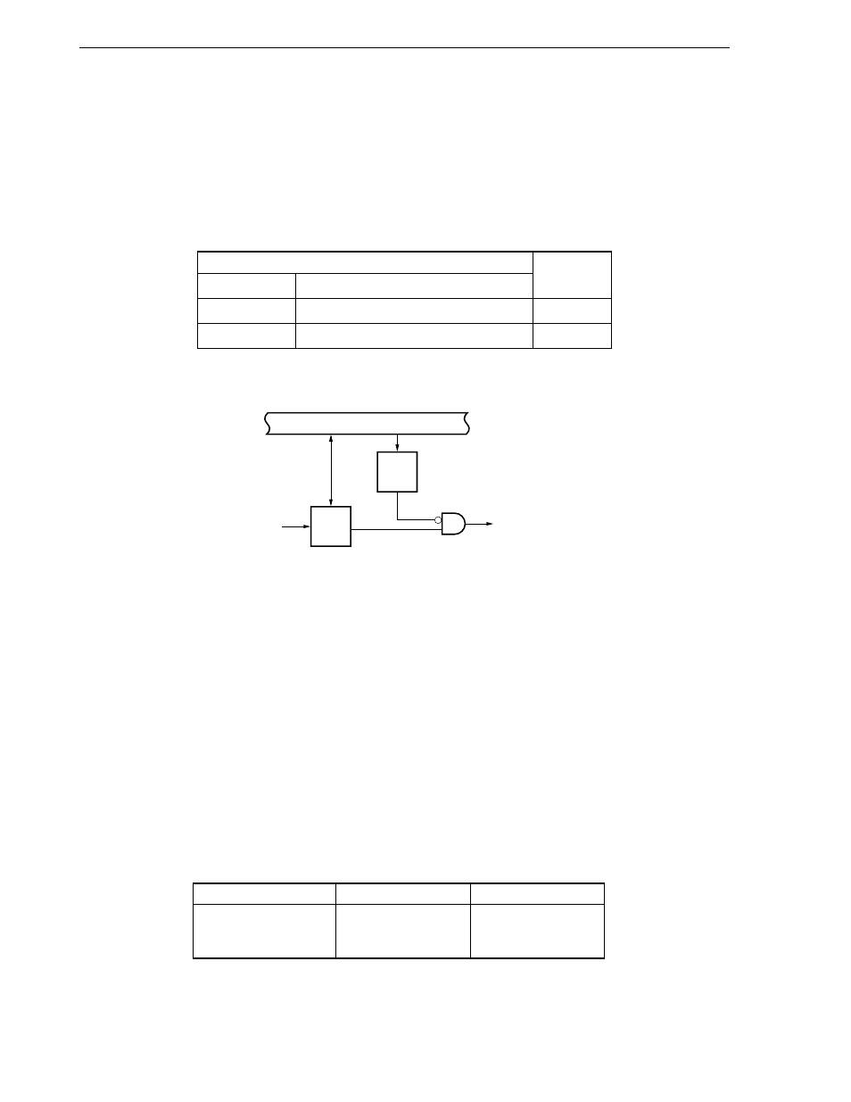
Internal bus
MK
IF
Test input
signal
Standby
release signal
21.5 Test Functions
When a clock timer overflow occurs and when the port 4 falling edge is detected, a corresponding test input flag
is set (1) and a standby release signal is generated.
Unlike the interrupt function, vector processing is not executed.
There are two test input factors as shown in Table 21-5. The basic configuration is shown in Figure 21-18.
Table 21-5. Test Input Factors
Test Input Factors
Name
Trigger
INTWT
Watch timer overflow
Internal
INTPT4
Falling edge detection at port 4
External
Figure 21-18. Basic Configuration of Test Function
Remark
IF : test input flag
MK: test mask flag
21.5.1 Registers controlling the test function
The test function is controlled by the following three registers.
• Interrupt request flag register 1L (IF1L)
• Interrupt mask flag register 1L (MK1L)
• Key return mode register (KRM)
The names of the test input flags and test mask flags corresponding to the test input signals are listed in Table
21-6.
Table 21-6. Flags Corresponding to Test Input Signals
Test Input Signal Name
Test Input Flag
Test Mask Flag
INTWT
WTIF
WTMK
INTPT4
KRIF
KRMK
Internal/
External