NEC PD78058FY(A) User Manual
Page 308
308
CHAPTER 16 SERIAL INTERFACE CHANNEL 0 (
µ
PD78058F SUBSERIES)
SCK0
"H"
SB0 (SB1)
SCK0
"H"
SB0 (SB1)
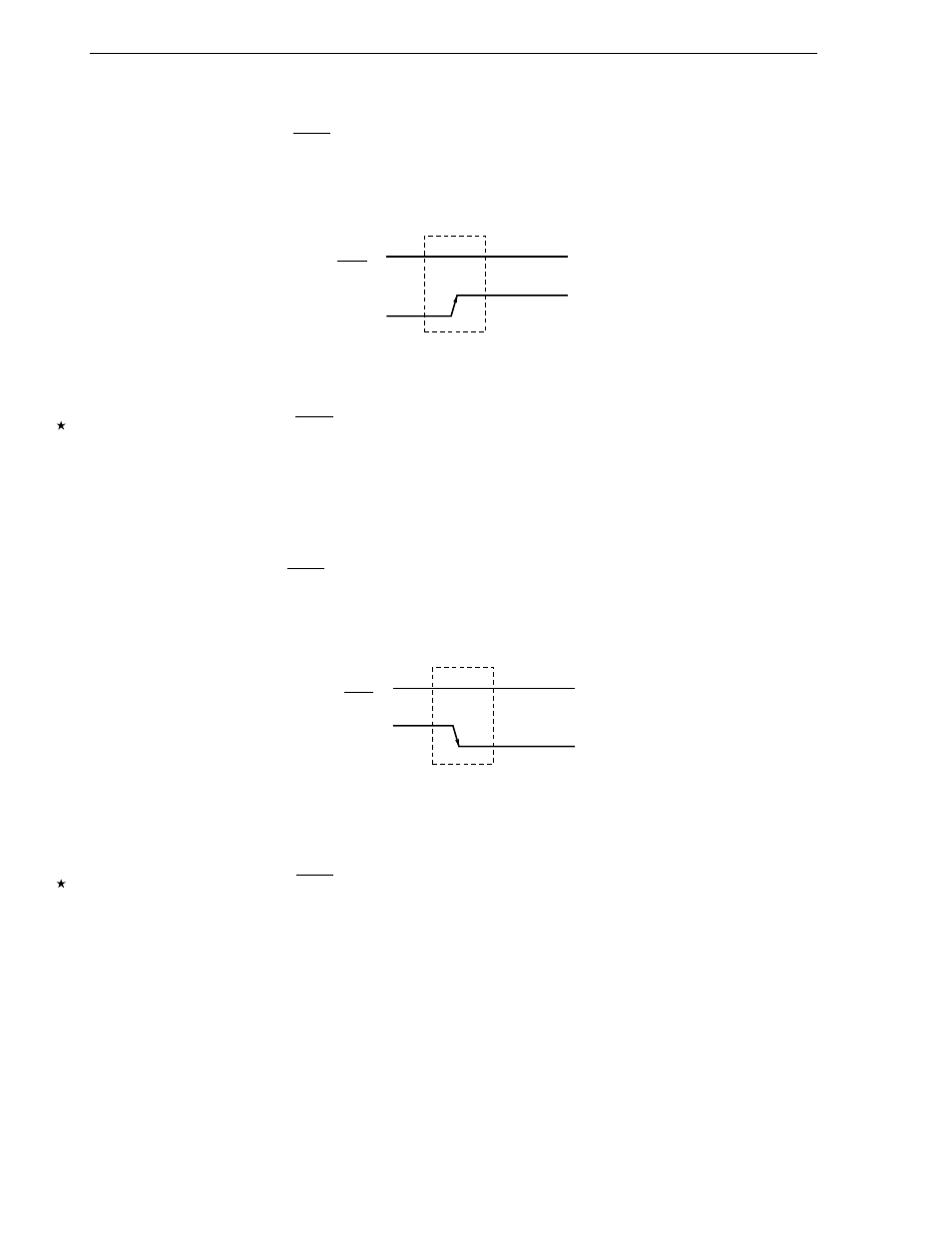
(a) Bus release signal (REL)
The bus release signal is a signal with the SB0 (SB1) line which has changed from the low level to the
high level when the SCK0 line is at the high level (without serial clock output).
This signal is output by the master device.
Figure 16-12. Bus Release Signal
The bus release signal indicates that the master device is going to transmit an address to the slave device.
The slave device incorporates hardware to detect the bus release signal.
Caution
When the SCK0 line is high level and the SB0 (SB1) changes from low level to high level,
this is recognized as a bus release signal. Therefore, if there are shifts in the bus change
timing due to influences such as the board capacity, this may be judged to be a bus
release signal even though data is being sent. Thus, much care is requiring in wiring.
(b) Command signal (CMD)
The command signal is a signal with the SB0 (SB1) line which has changed from the high level to the
low level when the SCK0 line is at the high level (without serial clock output). This signal is output by
the master device.
Figure 16-13. Command Signal
The command signal indicates that from this point, the master will send a command to the slave (however,
command signals following bus release signals indicate that an address will be sent).
The slave has incorporated the hardware for detecting command signals.
Caution
When the SCK0 line is high level and the SB0 (SB1) changes from high level to low level,
this is recognized as a command signal. Therefore, if there are shifts in the bus change
timing due to influences such as the board capacity, this may be judged to be a command
signal even though data is being sent. Thus, much care is requiring in wiring.