NEC PD78058FY(A) User Manual
Page 489
489
CHAPTER 21 INTERRUPT AND TEST FUNCTIONS
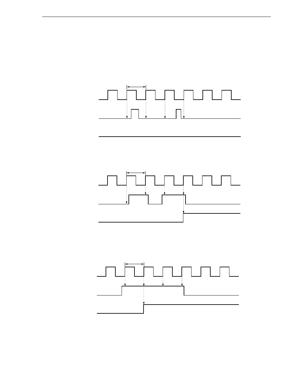
(b) When input is equal to or twice the sampling cycle (t
SMP
)
The noise elimination circuit sets the interrupt request flag (PIF0) at (1) when the sampled INTP0 input level
is active twice in succession.
Figure 21-8 shows the input/output timing of the noise elimination circuit.
Figure 21-8. Noise Elimination Circuit Input/Output Timing (During Rising Edge Detection)
(a) When input is less than the sampling cycle (t
SMP
)
(c) When input is twice or more than the cycle frequency (t
SMP
)
t
SMP
Sampling Clock
INTP0
PIF0
<2> is the second time in succession that sampling has found
the INTP0 level to be high, so the PIF0 flag is set at 1.
<1>
<2>
t
SMP
Sampling Clock
INTP0
PIF0
At the point when the level of INTP0 is found to be high the
second time in succession, the PIF0 flag is set at 1.
t
SMP
Sampling Clock
INTP0
PIF0
Since the level of INP0 is not high at any time when it is sampled,
the PIF0 output remains at the low level.