Data register – National Instruments SCXI-1163 User Manual
Page 50
Register Descriptions
Chapter 4
SCXI-1163 User Manual
4-4
© National Instruments Corporation
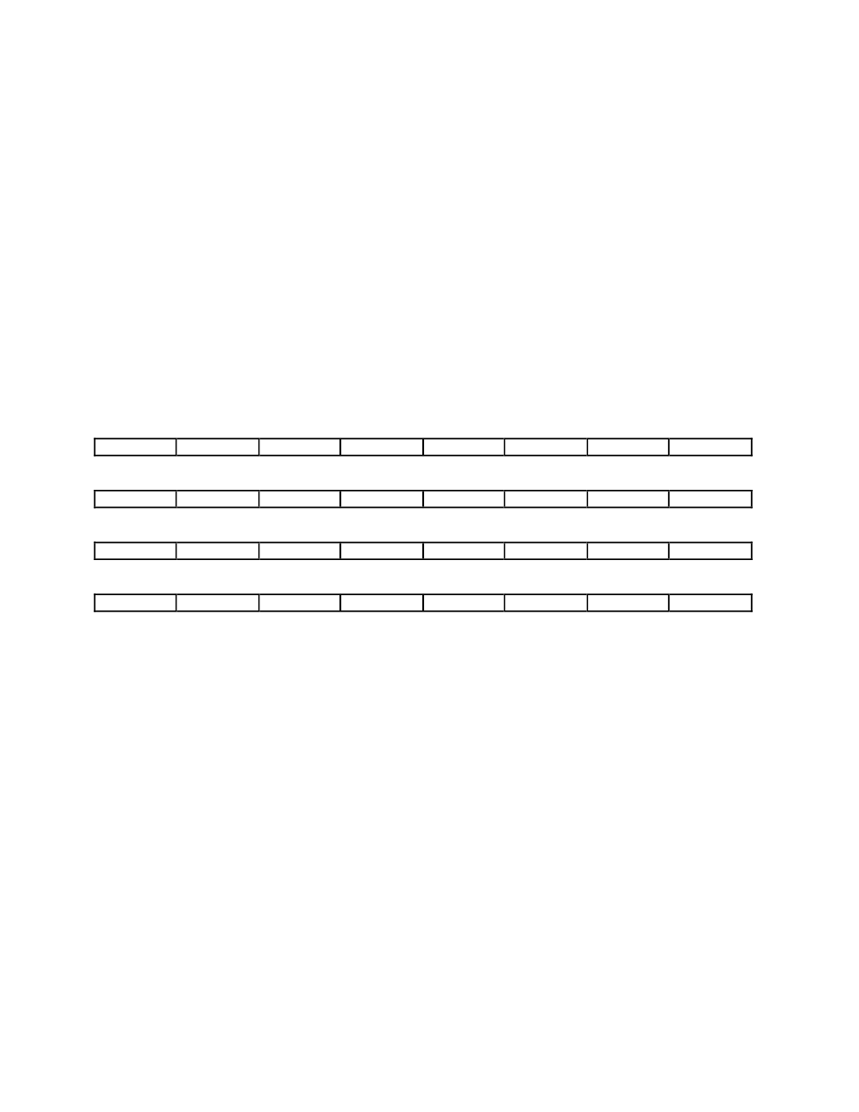
Data Register
The Data Register contains 32 bits that control the state of each output of the SCXI-1163.
Whenever the Data Register is selected by the Address Handler, the Data Register shifts in the
data present on the MOSI line, bit 31 first, and then latches the data when deselected. At power
up or at reset, the Data Register contains all logic highs. The Data Register has two addresses–
hexadecimal 0001 and 0006. After a write to address 0001, the Data Register drives the outputs
regardless of the jumper-set primary mode of operation (either serial or parallel). After a write to
address 0006, the Data Register drives the outputs only if the primary mode of operation is set to
serial; if the primary mode is set to parallel, the outputs are driven to the logic levels seen at the
rear connector.
Type:
Write-only
Word Size:
32-bit
Bit Map:
31
30
29
28
27
26
25
24
OUT(31)
OUT(30)
OUT(29)
OUT(28)
OUT(27)
OUT(26)
OUT(25)
OUT(24)
23
22
21
20
19
18
17
16
OUT(23)
OUT(22)
OUT(21)
OUT(20)
OUT(19)
OUT(18)
OUT(17)
OUT(16)
15
14
13
12
11
10
9
8
OUT(15)
OUT(14)
OUT(13)
OUT(12)
OUT(11)
OUT(10)
OUT(9)
OUT(8)
7
6
5
4
3
2
1
0
OUT(7)
OUT(6)
OUT(5)
OUT(4)
OUT(3)
OUT(2)
OUT(1)
OUT(0)
Bit
Name
Description
31-0
OUT<31..0>
Output (31 through 0) – Determine the state of the outputs.
If set to 0, the outputs are driven low. If set to 1, the
outputs are pulled high.