Figure 2-10, Scxi-1163 status register timing diagram – National Instruments SCXI-1163 User Manual
Page 39
Configuration and Installation Chapter 2
SCXI-1163 User Manual 2-24 © National Instruments Corporation
To read from a Status Register, follow these steps:
1. Initial conditions:
SS* asserted low.
SERDATIN = don't care.
DAQD*/A = 0.
= 1.
SERCLK = don't care.
2. The Status Registers are 1-bit read-only registers that indicate the primary or jumper-set
mode of operation and the mode of operation currently driving the outputs. The register at
address 0002 holds the Primary Mode Status; the register at address 0003 holds the Output
Mode Status. You do not need to pulse the SERCLK to read the Status Register.
Read the level of the SERDATOUT line. The level can be interpreted as follows:
• Primary Mode Status Register–a 1 indicates that the primary mode of operation is set for
parallel writes, and a 0 indicates that the primary mode of operation is set for serial
writes.
• Output Mode Status Register–a 1 indicates that the outputs are being set by the data
contents of the data register, and a 0 indicates that the outputs are being set by the levels
seen at the rear connector.
3. Pull DAQD*/A high. This disables further reads from the Status Register. If you want, you
can write address FFFF (hexadecimal) to the Address Handler. This selects the Parking
Register and makes the module registers more immune to noise.
4. Pull low to deassert the SS* line and establish conditions for writing a new slot-select
number to the Slot 0 Slot-Select Register.
5. If you are not selecting another slot, write zero to the Slot 0 Slot-Select Register.
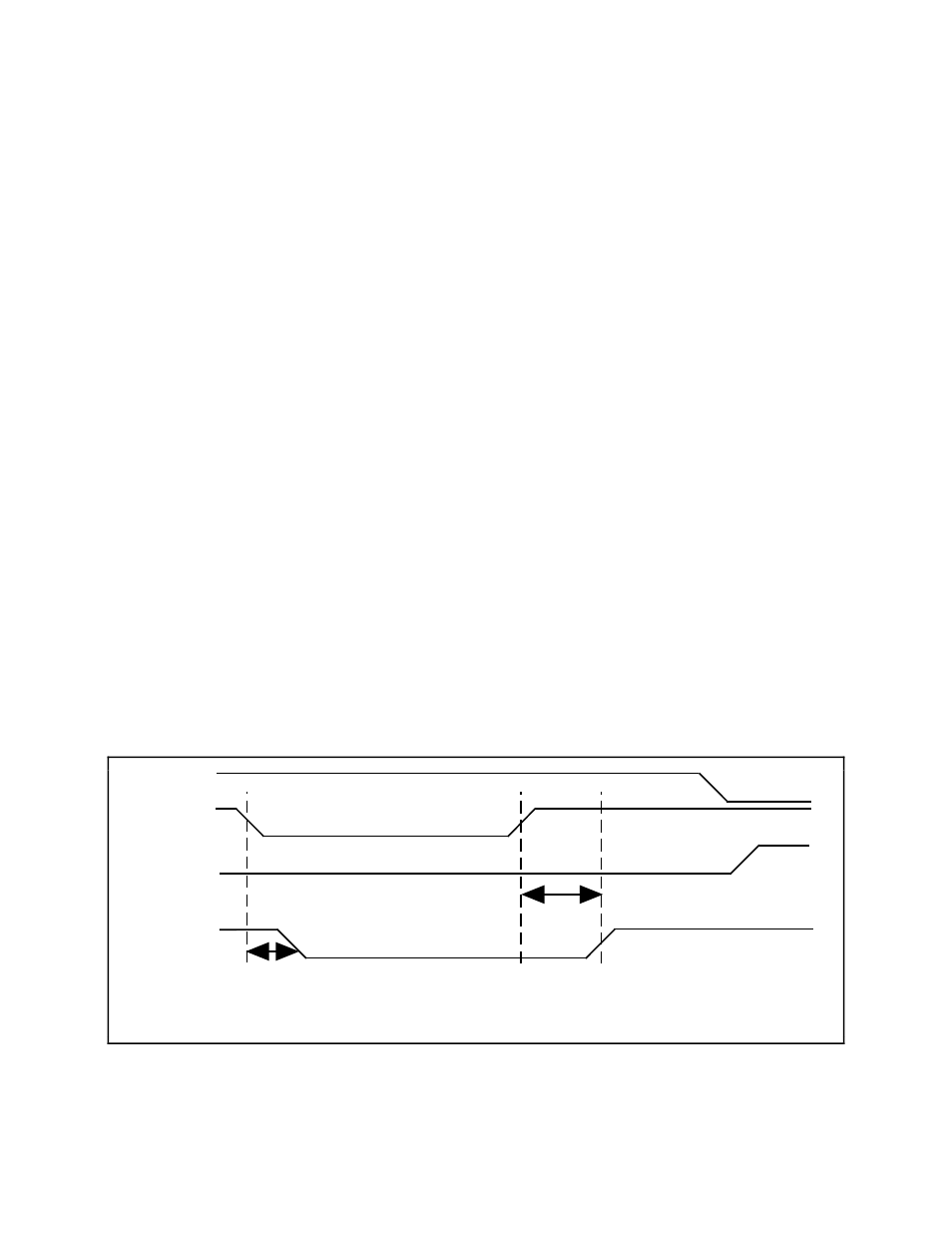
Figure 2-10 illustrates a read of an SCXI-1163 Status Register.
SS*
SERDATOUT
SLOT0SEL*
DAQD*/A
T
delay1
DAQD*/A low to SERDATOUT valid
75 nsec
T
delay2
DAQD*/A high to SERDATOUT high 650 nsec maximum
T
delay1
T
delay2
Figure 2-10. SCXI-1163 Status Register Timing Diagram
For further details on programming these signals, refer to Chapter 5,