Chapter 3 analog output, Figure 3-1. analog output block diagram, Analog output circuitry – National Instruments Data Acquisition Device E Series User Manual
Page 81: Dacs, Dac fifo, Analog output circuitry -1, Dacs -1 dac fifo -1, Analog output
© National Instruments Corporation
3-1
3
Analog Output
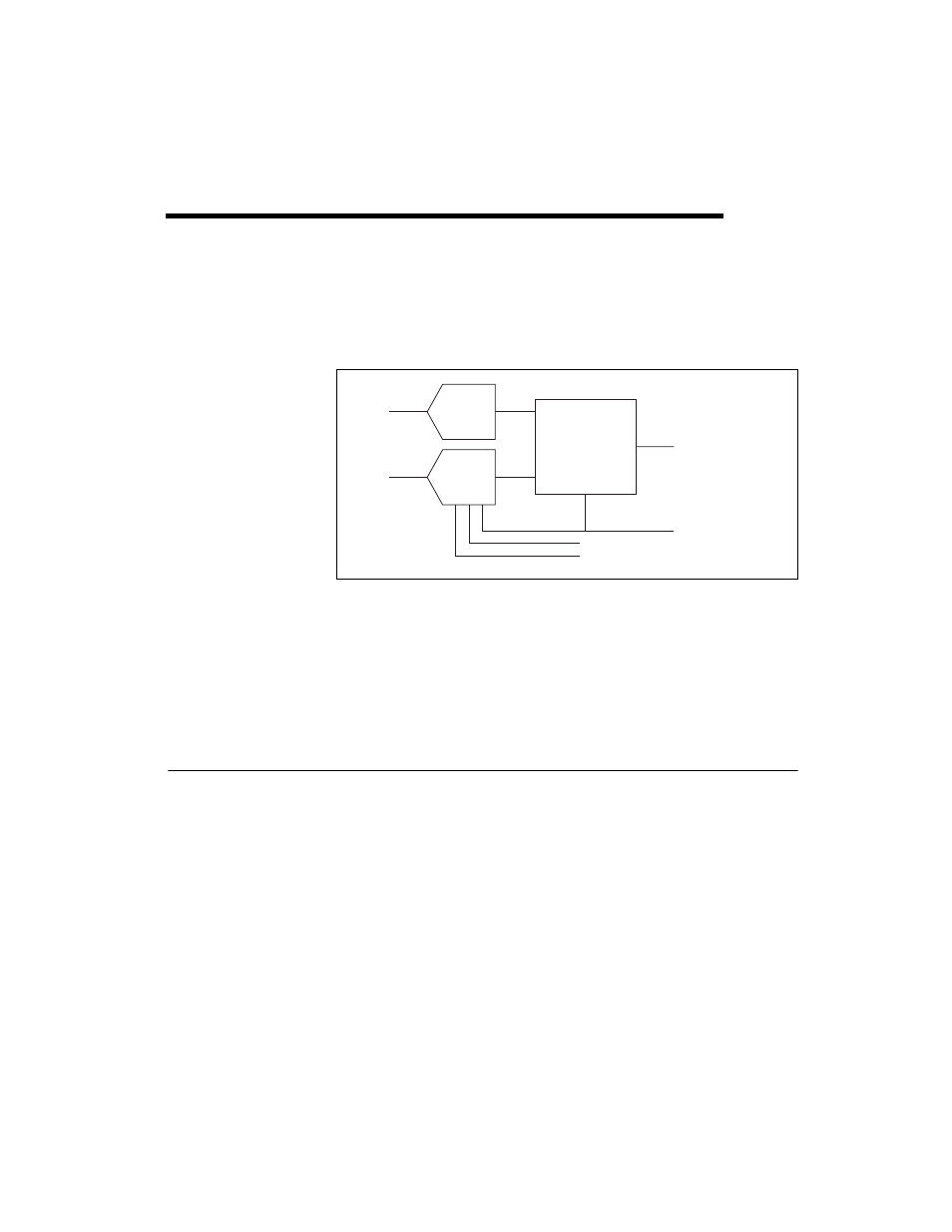
Figure 3-1 shows the analog output circuitry of E Series devices.
Figure 3-1. Analog Output Block Diagram
Many E Series boards have analog output functionality. E Series boards
that support analog output have two AO channels that are controlled by a
single clock and are capable of waveform generation. Refer to Appendix A,
, for specific information about the capabilities
of your device.
Analog Output Circuitry
DACs
Digital-to-analog converters (DACs) convert digital codes to analog
voltages.
DAC FIFO
The DAC FIFO enables analog output waveform generation. It is a
first-in-first-out (FIFO) memory buffer between the computer and the
DACs that allows you to download all the points of a waveform to your
board without host computer interaction.
AO 0
AO 1
DAC0
DAC1
AO FIFO
AO Data
AO Sample Clock
Polarity Select
Reference Select