Figure a-22. daqpad-6020e block diagram, Daqpad-6020e block diagram, Differential signals – National Instruments Data Acquisition Device E Series User Manual
Page 161
Appendix A
Device-Specific Information
A-26
ni.com
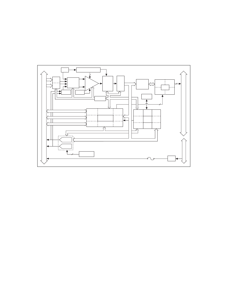
DAQPad-6020E Block Diagram
Figure A-22 shows a block diagram of the DAQPad-6020E.
Figure A-22. DAQPad-6020E Block Diagram
Connecting Signals to the DAQPad-6020E BNC
Analog Input
You can use each analog input BNC connector for one differential signal or
two single-ended signals.
Differential Signals
To connect differential signals, determine the type of signal source you are
using: a floating signal source or a ground-referenced signal source. Refer
to the
Differential Connection Considerations
sections of Chapter 2,
, for more information.
To measure a floating signal source, move the switch to the FS position. To
measure a ground-referenced signal source, move the switch to the GS
Timing
PFI / Trigger
I/O Connector
4
USB Connector
Exter
nal P
o
w
e
r
Digital I/O (8)
12-Bit
Sampling
A/D
Converter
EEPROM
Configuration
Memory
+
NI-PGIA
Gain
Amplifier
–
Calibration
Mux
Mux Mode
Selection
Switches
Analog
Muxes
Voltage
REF
Calibration
DACs
Dither
Circuitry
6
Calibration
DACs
5 V
Supply
DAC0
DAC1
1 A Fuse
DAQ - STC
Analog Input
Timing/Control
Analog Output
Timing/Control
Digital I/O
Trigger
Counter/
Timing I/O
Interrupt
Request
Bus
Interface
(8)
(8)
1
2
AI Control
Analog
Input
Control
EEPROM
Control
DAQ-PnP
DAQ-STC
Bus
Interface
Analog
Output
Control
Bus
Interface
Bus
Interface
USB
Port
USB Micro
Controller
Interrupt
Request
EEPROM
Control
IRQ
AO Control
Data (16)
Data (16)
Data
Transceivers
ADC
FIFO