Figure c-2 – National Instruments PC-LPM-16/PnP User Manual
Page 67
Appendix C Using Your PC-LPM-16 (Non-PnP) Board
National Instruments Corporation
C-7
PC-LPM-16/PnP User Manual
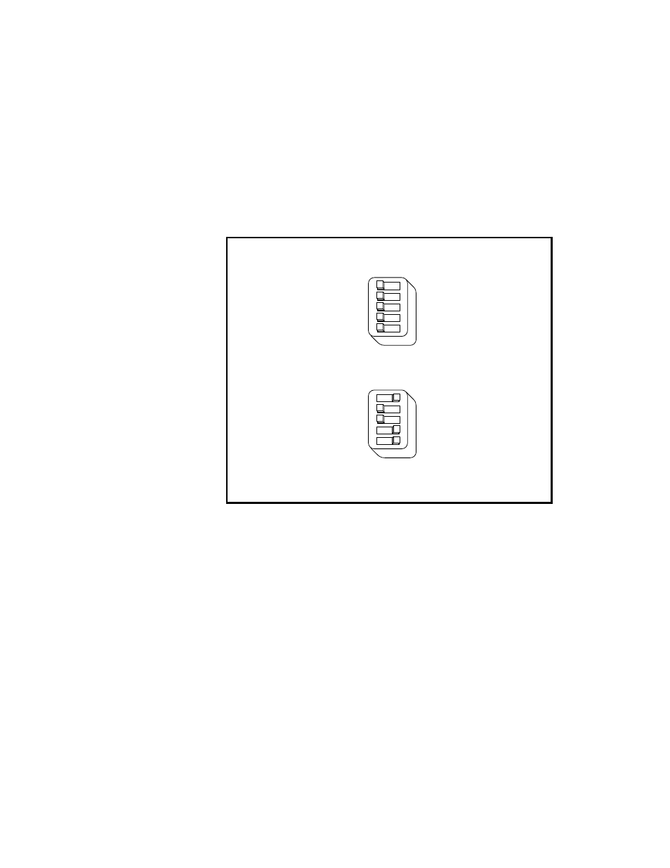
Each switch in U26 corresponds to one of the address lines A9 through
A5. Slide the switch to the side labeled
A9
to
A5
to select a binary value
of
zero
for the corresponding address bit. Slide the switch to the side of
the switch labeled
ON
to select a binary value of
one
for the
corresponding address bit. Figure C-2 shows two possible switch
settings.
Figure C-2.
Example Base I/O Address Switch Settings
The PC-LPM-16 decodes the five LSBs of the address (A4 through A0)
to select the appropriate PC-LPM-16 register. To change the base I/O
address:
1.
Remove the plastic cover on U26.
2.
Slide each switch to the desired position.
3.
Check each switch to verify that the switch is pressed entirely to the
side.
4.
Replace the plastic cover.
Note the new PC-LPM-16 base I/O address for use when configuring
the PC-LPM-16 software in the
Hardware and Software Configuration
Form
in Appendix E,
Customer Communication
–Slide to this side for 1
–Slide to this side for 0
a. Switches Set to Base I/O Address of Hex 000
b. Switches Set to Base I/O Address of Hex 260 (Factory Setting)
U26
A9
A8
A7
A6
A5
–Slide to this side for 1
–Slide to this side for 0
U26
A9
A8
A7
A6
A5