User menu, Time code> (continued), Video – Panasonic AJ-D650 User Manual
Page 34
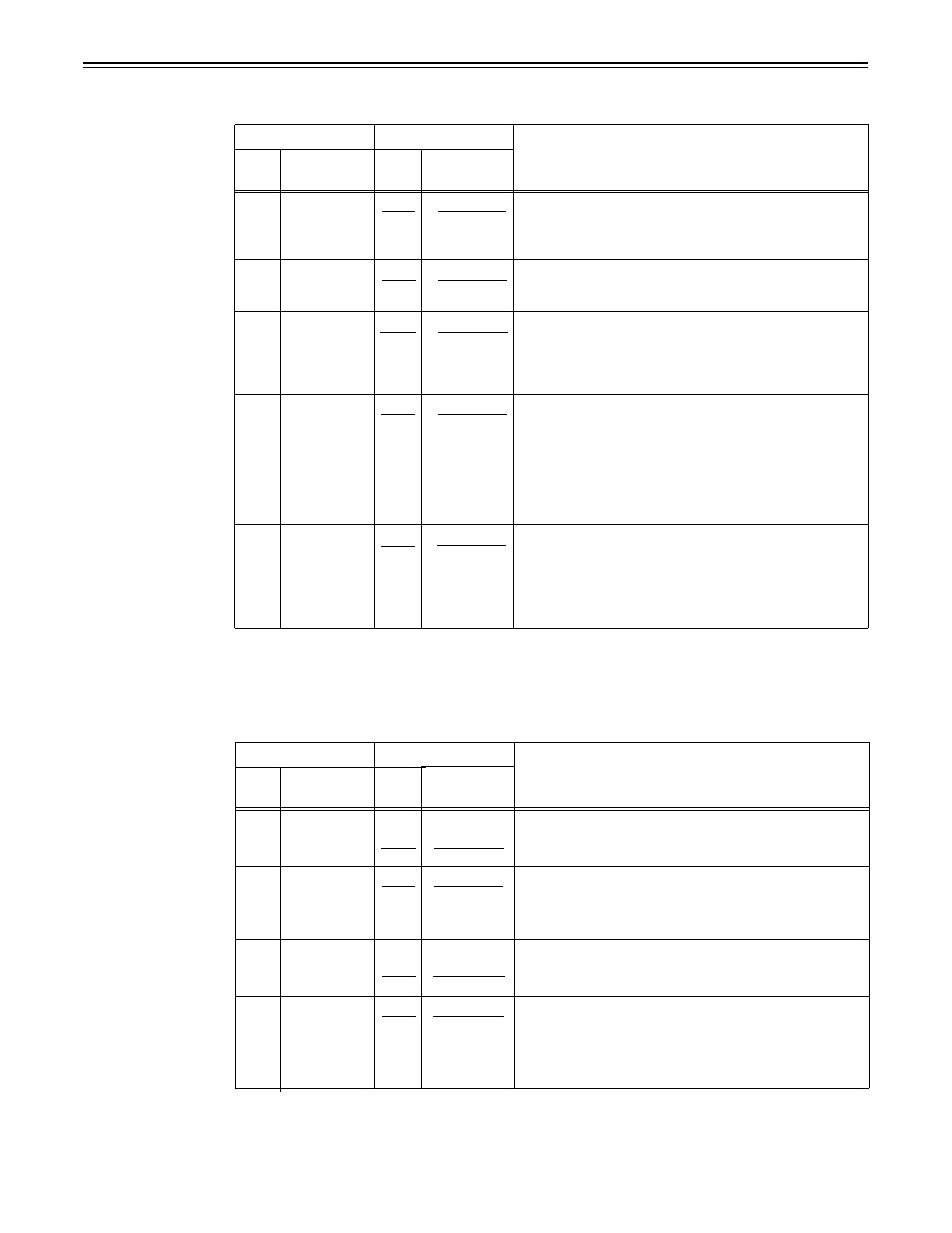
USER menu
Item
Setting
Superimposed
display
Superimposed
display
Description
This selects whether to control the phase correction of the
LTC generated by the TCG.
0: Phase correction control is not performed.
1: Phase correction control is performed.
This selects whether the CF flag of the TCG is to ON.
0: CF flag is OFF.
1: CF flag is ON.
This selects the DF/NDF mode for CTL and TCG.
0: Drop frame mode.
1: Non-drop frame mode.
No.509 is valid when the CONTROL is LOCAL or LOCAL
ENA of item 004 to “ENA”.
This selects the time code generator run mode.
0:
Generator runs only during recording.
1:
Generator runs during usual operation.
Even if “0” is selected, the time code generator runs during
usual operation when “1” is selected at the setting menu
No.504 (REGEN MODE).
This is used to switch the phase of the time code, which is
output from the TIME CODE OUT connector, for the external
LTC input when the TC INT/EXT switch is at the EXT
position. (In EE mode only)
0:
Time code is synchronized with output video signal.
1:
Time code is synchronized with external time code input.
No.
507
No.
0000
0001
PHASE
CORR
OFF
ON
TCG CF
FLAG
OFF
ON
508
509
510
0000
0001
0000
DF MODE
DF
0001
NDF
RUN MODE
0000
REC
0001
FREE
511
TC OUT
0000
V OUT
REF
0001
TC IN
The underline on the setting item denotes the initial setting.
USER menu
Item
Setting
Description
Superimposed
display
P
B
/P
R
IN LV
Superimposed
display
M
ΙΙ
B-CAM
No.
600
No.
0000
0001
This selects the component input signal level.
0: Mll level.
1: 0 cam level.
This selects whether to generate the internal black burst
signal.
0:
Signal is not generated.
1: Signal is generated.
601
INT BB
SIG
0000
OFF
0001
BB
INPUT
0000
B/W
C KILL
0001
AUTO
This selects color killer processing for the video input signals.
0: The signals are forcibly processed as B/W signals.
1:
The signals are automatically processed.
This selects whether to float the vertical sync position of the
video output in order to align the video output phase with the
input in the EE/record/edit modes.
0:
Signals are not floated.
1: Signals are floated.
602
603
OUT
0000
N-VF
VSYNC
0001
VF
The underline on the setting item denotes the initial setting.
– 3 4 –