Panel mounting procedure – Panduit DPOE24S1X User Manual
Page 56
PANDUIT
® DPoE™ Power Patch Panel User’s Guide
Issue 2.2
Part Number: PN378A
55
IMPORTANT:
The DPOE™ Power Patch Panel Installation Worksheet should be used to record
pertinent information when installing DPoE™ Power Patch Panel(s), particularly if
the PANDUIT
®
Element Manager is monitoring the network. (See page 29,
Provisioning the Panel,
for more information on how this information will be
entered in the EM.) The installer should complete this worksheet.
Panel Mounting Procedure
WARNING:
Only trained and qualified service personnel should install or service
DPoE
™ Power Patch Panels
WARNING:
Before installing or servicing DPoE™ Power Patch Panels or
communication wiring, be aware of the hazards with the associated
electrical circuitry.
Rack Mounting Instructions
1. Record the MAC address, printed on a
sticker on the back of the unit, by
writing it in the space provided on the
included Installation Worksheet
(PANDUIT part number PN377).
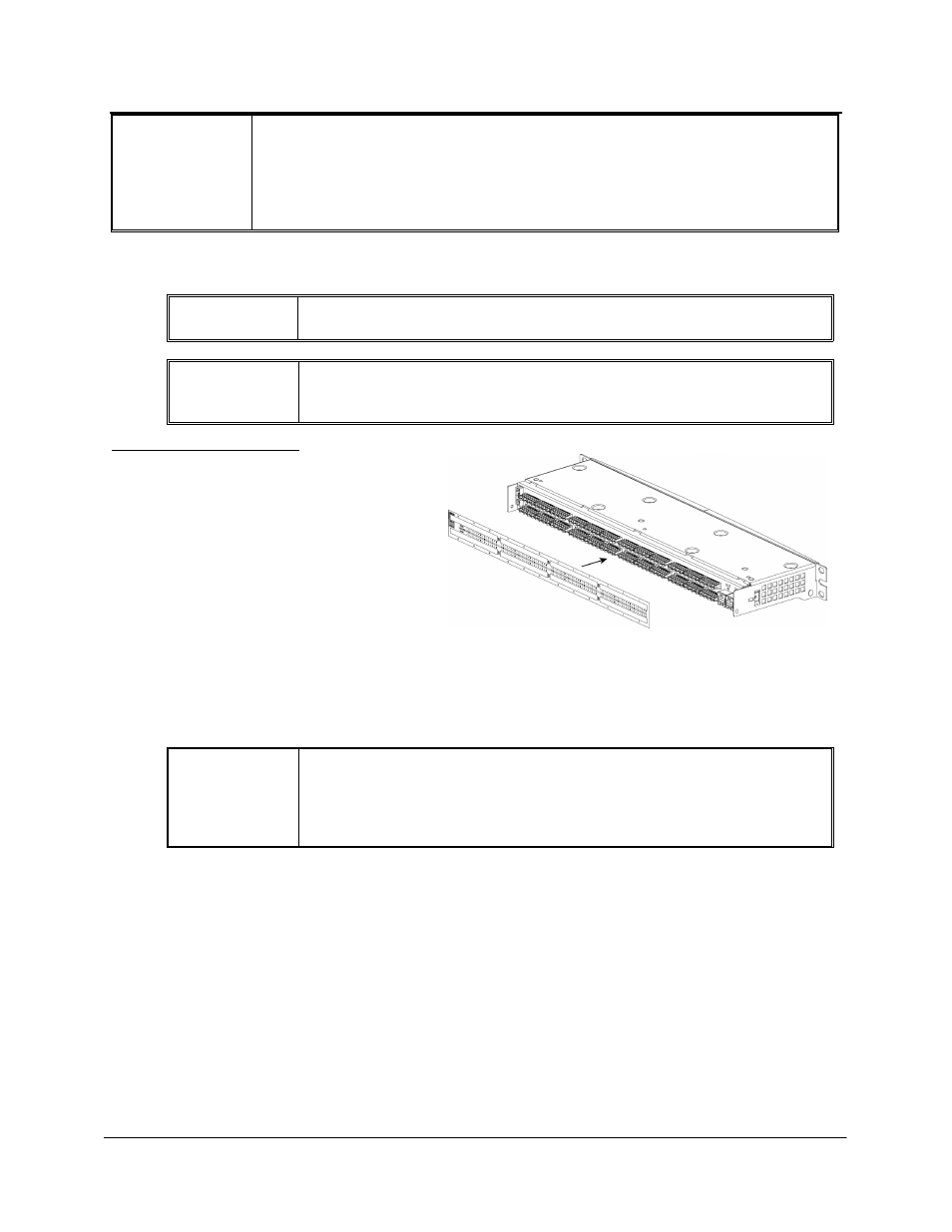
2. Slip the Wiring Template Label over
the rows of connectors on the back of
the DPoE™ Power Patch Panel,
making sure the proper wiring color
code is facing out and that the writing
is not upside down. One side of the label indicates EIA/TIA 568A wiring, while the other side is
EIA/TIA 568B.
3. Using four of the enclosed metric screws, install the PANDUIT® DPoE™ Shielded Power Patch
Panel into the 19” rack at the planned rack position.
WARNING:
The supplied screws are part of a grounding system to ensure that the
DPoE
™ Power Patch Panel is properly grounded to the rack.
USE ONLY THE SUPPLIED SCREWS TO ATTACH THE PANEL TO
THE RACK.