Paradyne 8510 User Manual
Page 51
3. DSL Card Configuration
8000-A2-GB26-50
April 2001
3-15
IDSL Ports (DSL Parameters) 8303 IDSL Card
(continued)
A-B-B
8304 IDSL Card
A-B-A
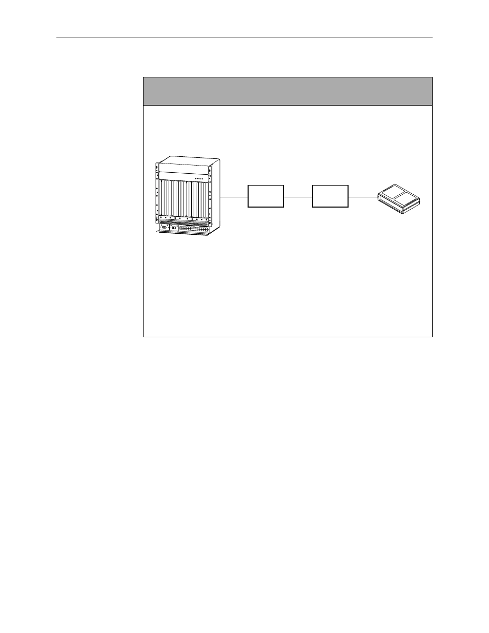
For data: The BRITE card on the channel bank connected to the GranDSLAM must be set
to NT. Set the channel bank card closest to the customer premises to LT. The IDSL Router
defaults to NT. This configuration allows handshaking across the line to start up correctly.
See the figure below:
Thresholds for Trap Messages:
Link Down Ct: – Sends a trap message if the number of DSL link down events in
15 minutes exceeds the selected value. Enter a value for the Link Down Count Trap (0
to 1000, or D to Disable). (Default = D)
NOTE: If you have made changes to this screen, exit the screen, then save the
changes. The changes are then activated. You can only save changes on one port at a
time.
Table 3-2.
Ports Options (8 of 9)
GranDSLAM
ALARMS
Major Minor
Fan
B
A
POWER
SERIAL
SMCM
CLOCK
A
ALARM
2
4
6
8
10
12
14
16
18
1
3
5
7
9
11
13
15
17
LAN/WAN SLOT
B
CLOCK
B
A
SERIAL
MCC
AC
ALARM
48V R
T
N
48V NEG
POWER ENTRY MODULE
LEFT UNIT: LINE A
RIGHT UNIT: LINE B
WARNING! POWER MUST BE DISCONN
ECTED AT THE SOURCE
BEFORE REMOVING OR INSTALLING THIS PW
R ENTRY MODULE
48V R
T
N
48V NEG
POWER ENTRY MODULE
LEFT UNIT: LINE A
RIGHT UNIT: LINE B
WARNING! POWER MUST BE DISCONN
ECTED AT THE SOURCE
BEFORE REMOVING OR INSTALLING THIS PW
R ENTRY MODULE
Channel
Bank
Digital
Carrier
System
LT NT
Hotwire
IDSL
Router
LT
NT
01-16949
Channel
Bank