Powerware 30-160kVA User Manual
Page 33
A---9
Powerware 9315 Maintenance Bypass Module 30---160kVA
164201177 Rev. C 041500
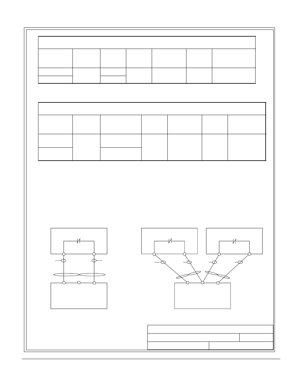
Table C--2. Control Wiring Requirements and Termination Requirement for
Reverse Transfer (RT) System.
Connecting Point
in MBM Cabinet
Size of
Pressure
Termination
(lb-in)
Connection
Point in UPS
Size of
Pressure
Termination
(lb-in)
Recommended
Wire Size
Maximum
Voltage and
Current
Remarks
TB1---12
#18---#8
TB6---1
#18---#8
#18 #14
120VAC
See Fig 1.
TB1---14
#18 #8
(55)
TB6---2
#18 #8
(55)
#18---#14
120VAC
1.0A
See Fig 1.
(Twisted Pair)
Table C--3. Control Wiring Requirements and Termination Requirement for
Parallel Redundant System.
Connecting Point
in MBM Cabinet
Size of
Pressure
Termination
(lb-in)
Connection Point
in UPS
Size of
Pressure
Termination
(lb-in)
Recommended
Wire Size
Maximum
Voltage and
Current
Remarks
TB1---12
TB1---13
#18---#8
TB6---1 (UPS1)
TB6---1 (UPS2) #18---#8
#18 #14
120VAC
See Fig 2.
TB1---13
TB1---14
#18 #8
(55)
TB6---2 (UPS1)
TB6---2 (UPS2)
#18 #8
(55)
#18---#14
120VAC
1.0A
See Fig 2.
(Twisted Pair)
NOTES FOR TABLES C--2 AND C--3:
·
Install the copper wiring in a conduit separate from the power wiring.
·
Control wiring is NEC Class 1.
·
Control wiring from each UPS Module should be twisted.
DESCRIPTION:
DATE:
DRAWING NO:
2 of 2
SHEET:
REVISION:
C
041500
164201177---1
INSTALLATION NOTES
UPS
MBM
TB1
TB6
---1
---2
---12
---13
---14
K3
Twist Pair
BLK
WHT
UPS1
MBM
TB1
TB6
---1
---2
---12 ---13
---14
K3
Twist Pair
BLK
WHT
UPS2
TB6
---1
---2
K3
BLK
WHT
Twist Pair
Figure 1. (Reverse Transfer)
Figure 2. (Parallel Redundant)