A, b, c, d – Powerware 30-160kVA User Manual
Page 27
DESCRIPTION:
DATE:
DRAWING NO:
2 of 4
INSTALLATION NOTES
SHEET:
REVISION: C
164201177---1
041500
A---3
Powerware 9315 Maintenance Bypass Module 30---160kVA
164201177 Rev. C 041500
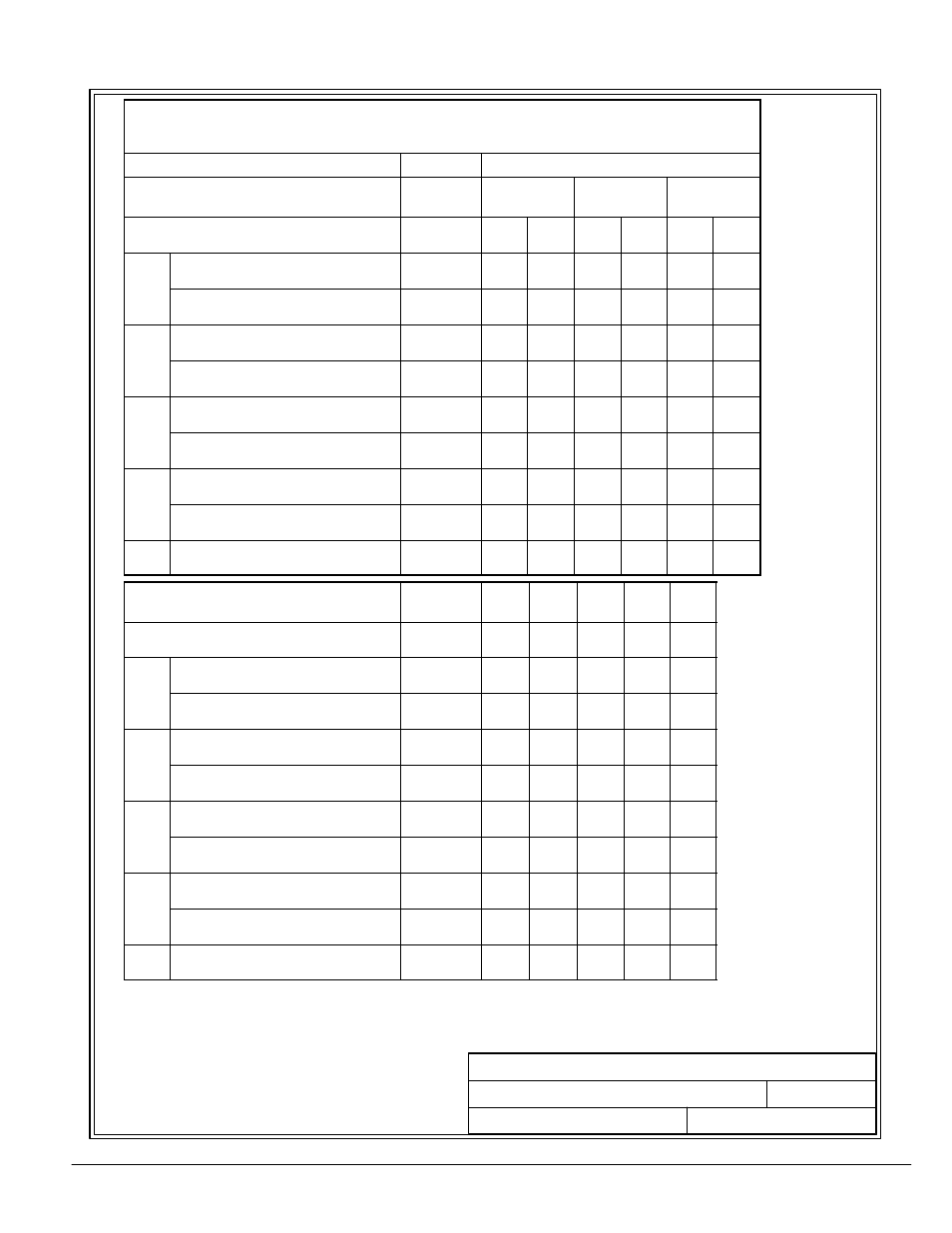
Table A--2. Ratings & External Wiring Requirements for
Powereware 9315
MBM 30---160
kVA
, 480:480
VAC
/600:600
VAC
Rating and External Wiring Requirement
Units
Rating 60 Hz
Basic unit rating at
0.8 lagging PF load
KVA
KW
160
128
130
104
100
80
UPS Input Voltage/Bypass Input
UPS Output Voltage
VOLTS
VOLTS
480
480
600
600
480
480
600
600
480
480
600
600
A
AC Input to Maintenance Bypass
(3) Phases, (1) Ground
AMPS
192
153
156
125
120
96
A
Conductor Size
Number per Phase
AWG/MCM
(each)
300
(1)
300
(1)
300
(1)
300
(1)
300
(1)
300
(1)
B
AC Input to UPS Bypass
(3) Phases, (1) Ground
AMPS
192
153
156
125
120
96
B
Conductor Size
Number per Phase
AWG/MCM
(each)
300
(1)
300
(1)
300
(1)
300
(1)
300
(1)
300
(1)
C
AC Output to Critical Load
(3) Phases, (1) Neutral, (1) Ground
AMPS
192
153
156
125
120
96
C
Conductor Size
Number per Phase
AWG/MCM
(each)
300
(1)
300
(1)
300
(1)
300
(1)
300
(1)
300
(1)
D
UPS/PTC Output to MBM Cabinet (MIS)
(3) Phases, (1) Neutral, (1) Ground
AMPS
192
153
156
125
120
96
D
Conductor Size
Number per Phase
AWG/MCM
(each)
300
(1)
300
(1)
300
(1)
300
(1)
300
(1)
300
(1)
E
Control Wiring to UPS
(2) Conductors
VOLTS
AMPS
120
1
120
1
120
1
120
1
120
1
120
1
Basic unit rating at
0.8 lagging PF load
KVA
KW
80
64
65
52
50
40
40
32
30
24
UPS Input Voltage/Bypass Input
UPS Output Voltage
VOLTS
VOLTS
480
480
480
480
480
480
480
480
480
480
A
AC Input to Maintenance Bypass
(3) Phases, (1) Ground
AMPS
96
78
60
48
36
A
Conductor Size
Number per Phase
AWG/MCM
(each)
1
(1)
1
(1)
1
(1)
1
(1)
1
(1)
B
AC Input to UPS Bypass
(3) Phases, (1) Ground
AMPS
96
78
60
48
36
B
Conductor Size
Number per Phase
AWG/MCM
(each)
1
(1)
1
(1)
1
(1)
1
(1)
1
(1)
C
AC Output to Critical Load
(3) Phases, (1) Neutral, (1) Ground
AMPS
96
78
60
48
36
C
Conductor Size
Number per Phase
AWG/MCM
(each)
1
(1)
1
(1)
1
(1)
1
(1)
1
(1)
D
UPS/PTC Output to MBM Cabinet (MIS)
(3) Phases, (1) Neutral, (1) Ground
AMPS
96
78
60
48
36
D
Conductor Size
Number per Phase
AWG/MCM
(each)
1
(1)
1
(1)
1
(1)
1
(1)
1
(1)
E
Control Wiring to UPS
(2) Conductors
VOLTS
AMPS
120
1
120
1
120
1
120
1
120
1
Note:
Callout letters
A, B, C, D,
and
E
Map to drawing 164201177---4 (Reverse Transfer Connection) and
164201177---7 (Parallel Connection). Read and understand the notes on drawings when planning your installation.