Powerware 30-160kVA User Manual
Page 16
12
Powerware 9315 Maintenance Bypass Module 30-160kVA
164201177 Rev. C 041500
Refer to the following while installing the MBM:
·
Dimensions in this manual are in millimeters and (inches).
·
Do not tilt the unit more than
10˚ during installation.
·
Remove the conduit landing plates to add conduit landing holes as required.
Plate material is 16 gauge steel (0.06 in. thick).
·
Terminals are UL and CSA rated at 90˚C. A hex key tool is required to attach
wires to the terminals.
·
Details about power wiring are provided in the tables of Appendix A of this
manual.
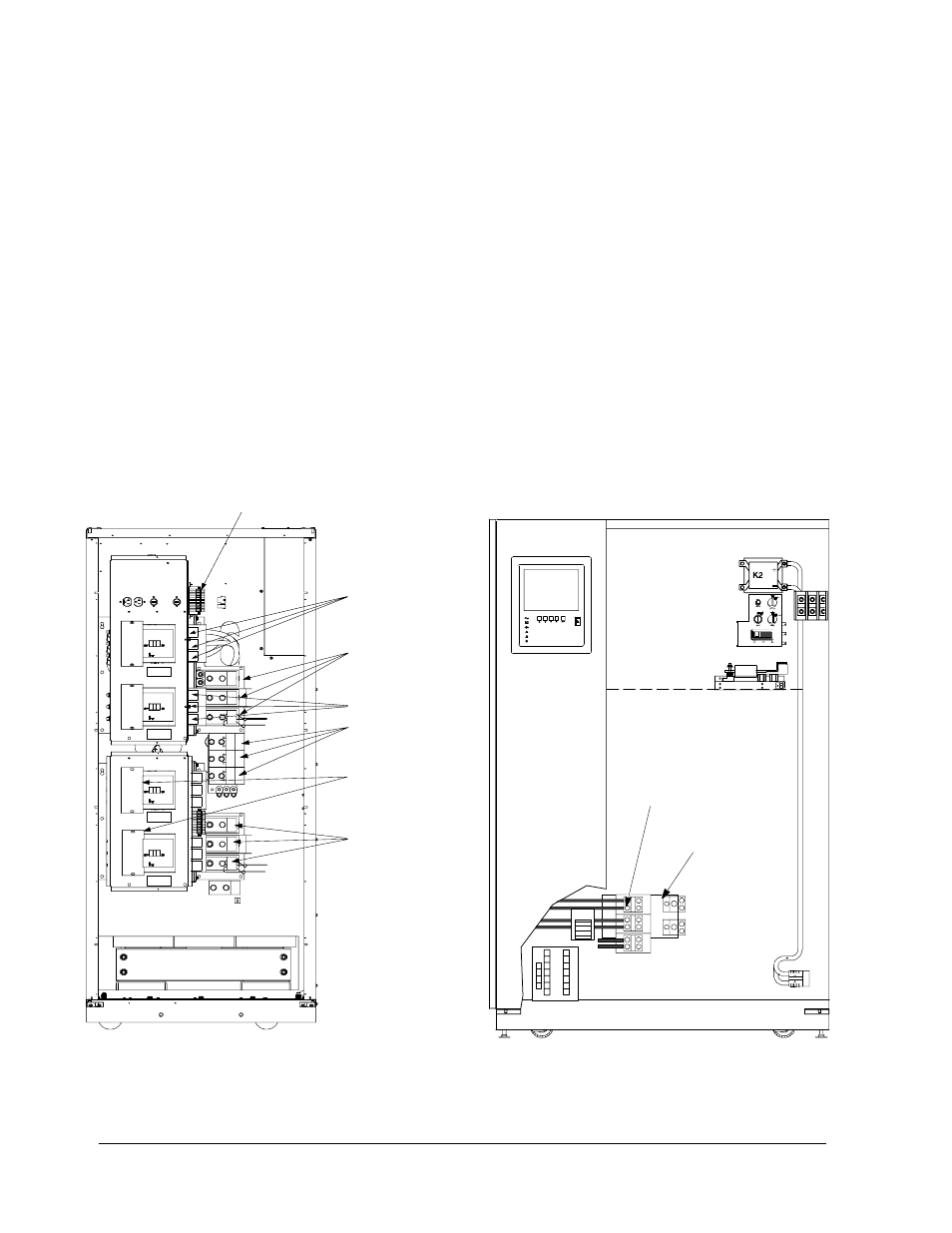
Figure 6 shows typical power wiring terminations of the UPS module and
Maintenance Bypass Module (30---160kVA). Refer to the Powerware 9315
Installation manual provided with the UPS system for location of UPS module
cabinet wiring terminations.
NOTE: Material and labor for external wiring are to be provided by designated
personnel.
LEFT DOOR
Output
Neutral
Connection
(E12)
TB1
A/C Output
E9, E10, E11
UPS MODULE
Maintenance Bypass Module
(30--160kVA UPS Shown)
TB2
RIGHT DOOR
REMOVED
FOR
CLARITY
MBP
MIS
BIB1
BIB2
BREAKER ANNUNCIATION
CRITICAL LOAD
CONNECTIONS
NEUTRAL
CONNECTIONS
OPTIONAL UPS
BYPASS
INPUT CONNECTIONS
UTILITY INPUT,
IF BIB BREAKER
INSTALLED
UPS/PTC OUTPUT
CONNECTION
UTILITY INPUT,
IF BIB BREAKER
IS NOT
INSTALLED
Figure 6. Typical Power Wiring Terminations of UPS Module and
Maintenance Bypass Module (30---160kVA)