1 ups control logic, Sola 4000 - pcb description, 2 rectifier – Powerware Uninterruptible Power Supply SOLA 4000 User Manual
Page 94
SOLA 4000 - PCB Description
JUE 401268
94
1.2 Rectifier
The rectifier control logic consists of two PCBs.
IF/PS - R
Rectifier electronic power supply
• input voltage sensing
• rectifier electronics power supply
CPHC16 - R
Rectifier control and regulation
• rectifier output voltage regulation
• rectifier output current limitation
• soft-start control
• battery charging current limitation
• generation of the thyristor firing pulses
• input voltage monitoring (phase rotation, mains failure)
• control for parallel rectifiers (with a common battery)
• 12-pulse rectifier control
• Second level current limitation for diesel-generators.
• Boost charging according to DIN 41773.
• Thermal compensation.
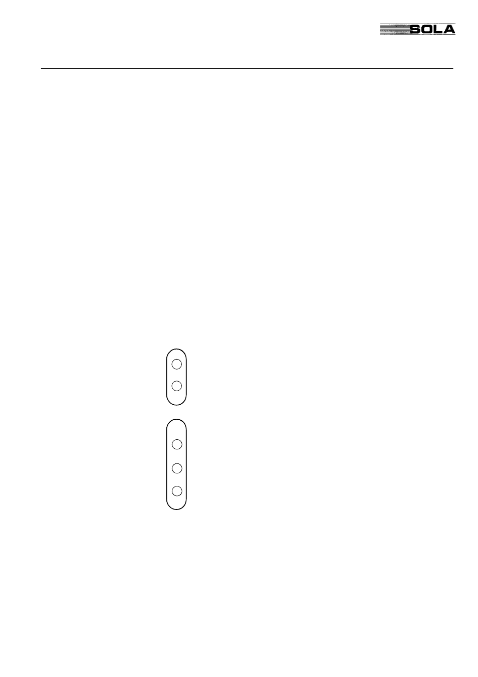
IF/PS - R Front View
FIG. 1.1 illustrates the LEDs of the IF/PS - R PCB which are
accessible from the front.
•
+ 12V analog circuits power supply OK
•
+ 16V microprocessor power supply unregulated
•
+ 12V interfaces power supply
•
+ 15V auxiliary LEM power supply (illuminated only for 12
pulse configuration)
•
- 15V auxiliary LEM power supply (illuminated only for 12 pulse
configuration)
PSPA
PSPP
- 15
+ 15
PSPA1
1 UPS Control Logic