2 operating panel, Sola 4000 - general system description, 2operating panel 2.1 functional description – Powerware Uninterruptible Power Supply SOLA 4000 User Manual
Page 12: 2 remote monitoring, 3 emergency power off
SOLA 4000 - General System Description
JUE 401264
12
2
OPERATING PANEL
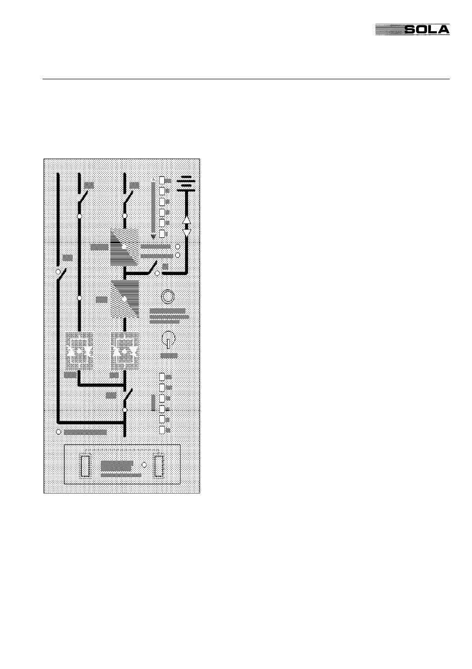
2.1 Functional Description
The operating panel is the user-interface of the UPS. It offers the
following functions:
• Indication of important data (actual load, battery charging
status, battery autonomy during the "BACK UP" phase)
• Protective functions ( Battery Running Down, Battery Test)
• Indication of the UPS operating mode
• Alarm signalling (audible and visual)
• Start push button
• Reset function after retransfer blocked condition
• Emergency-Power-Off function
The panel can be subdivided in four functional sections:
1. Block diagram with status LEDs
2. Battery autonomy and charging status
3. Percentage of load supplied
4. E.P.O. push-button
2.2 Remote Monitoring
The operating panel provides an option to communicate with a
computer through RS232 and RS485 interfaces. The RS232 serial
interface communicates with a PC or mainframe computer, with a
SNMP protocol (SEC). With the RS485 interface it is possible to
transmit all necessary data up to a distance of 400m or to connect
a remote monitoring panel.
2.3 Emergency Power Off
In case of emergency it is possible to switch off the entire UPS
system. This is done by simultaneously pressing the "Emergency
Power Off" (E.P.O.) push-buttons located on the operating panel.
This function provides UPS disconnection from the load and the
battery, when a separate shunt-trip battery circuit breaker is in-
stalled.
In the case of parallel and hot-standby configurations, activating
E.P.O on one unit, automatically switches OFF the entire system
(when IUG is closed on that unit).
2 Operating Panel