Adding a video cassette recorder (vcr) – Panasonic DIGA DMR-EZ27 User Manual
Page 51
51
RQT8851
Connection and Setting
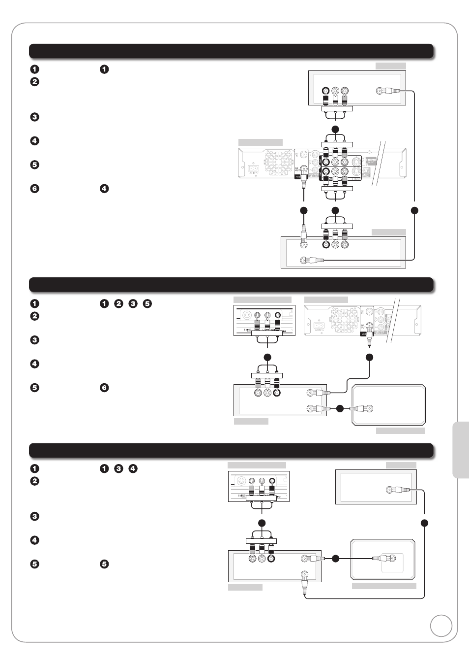
Adding a Video Cassette Recorder (VCR)
Additional coaxial cable and audio/video (AV) cable are required.
Connecting to a Television and a VCR (No Cable Box or Satellite Receiver)
Perform step on page 47.
Coaxial cable
(included) from the “RF OUT”
on the VCR to the “
VHF/UHF RF IN” on the
TV.
Audio/video cable
(included) from the
“
OUT” on the unit to the “AV IN” on the TV.
Coaxial cable from the “
RF OUT” on the unit
to the “
RF IN” on the VCR.
Audio/video cable from the “
IN1” on the
unit to the “
AV OUT” on the VCR.
Perform step on page 47.
AUDIO OUT
R L
VIDEO
OUT
RF IN
RF OUT
VHF/UHF
RF IN
AUDIO IN
R L
VIDEO
IN
step
2
step
4
step
5
Red White Yellow
Red White Yellow
Rear of TV
Rear of this unit
Rear of VCR
AUDIO IN
R L
VIDEO
IN
step
3
Red White Yellow
Red White Yellow
Connecting to a Television, a Cable Box and a VCR
Perform step , , , on page 48.
Coaxial cable from the “
RF OUT” on the unit
to the “
RF IN” on the VCR.
Coaxial cable from the “
RF OUT” on the
VCR to the “
RF IN” on the cable box.
Audio/video cable from the “
AV OUT” on
the VCR to the “
IN2” on the unit.
Perform step on page 48.
AUDIO OUT
L R
VIDEO
OUT
RF IN
RF OUT
RF IN
step
4
Yellow White Red
Yellow White Red
step
2
step
3
Rear of VCR
Rear of Cable Box
Rear of this unit
This unit’s front panel
Connecting to a Television, a Satellite Receiver and a VCR
Perform step , , on page 49.
Coaxial cable
(included) from the “RF OUT”
on the satellite receiver to the “
RF IN” on
the VCR.
Coaxial cable from the “
RF OUT” on the
VCR to the “
VHF/UHF RF IN” on the TV.
Audio/video cable from the “
AV OUT” on
the VCR to the “
IN2” on the unit.
Perform step on page 49.
RF OUT
VHF/UHF
RF IN
AUDIO IN
R L
VIDEO
IN
step
3
Rear of VCR
Rear of Satellite Receiver
Rear of TV
This unit’s front panel
AUDIO OUT
L R
VIDEO
OUT
Yellow White Red
Yellow White Red
step
4
RF IN
RF OUT
step
2
•