Determine pool heater location – Lochinvar EnergyRite ER302 User Manual
Page 9
Installation & Operation Manual
1
Determine pool heater location
(continued)
9
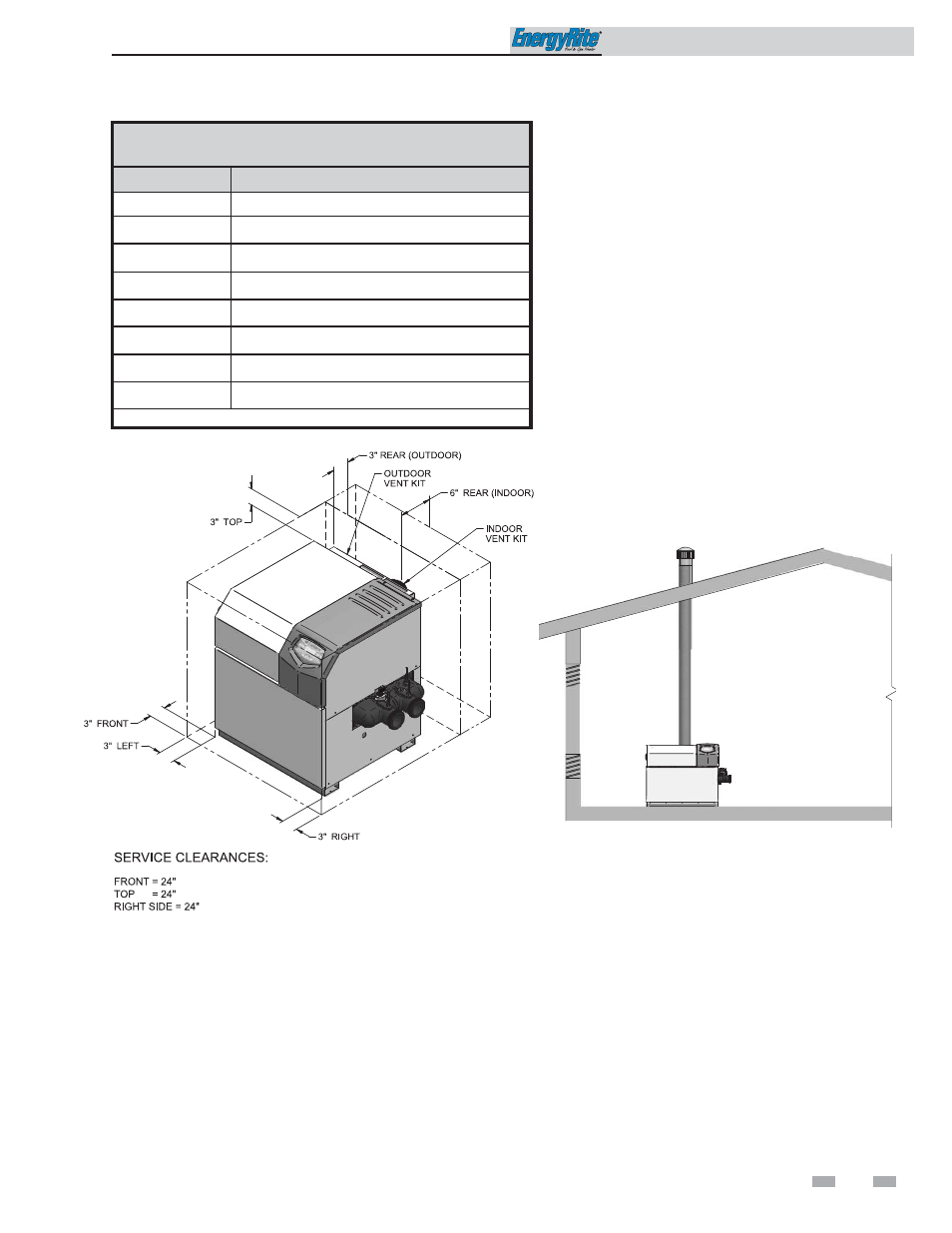
Figure 1-1_Clearances from Combustible Construction
(Front and Rear)
Combustion and ventilation air
requirements for conventionally
vented appliances and sidewall
vented appliances
Provisions for combustion and ventilation air must be
in accordance with the Air for Combustion and
Ventilation Section of the latest edition of the National
Fuel Gas Code, ANSI Z223.1, in Canada CAN/CGA-
B149 Installation Code for Gas Burning Appliances
and Equipment, or applicable provisions of the local
building codes.
The equipment room MUST be provided with
properly sized openings to assure adequate
combustion air and proper ventilation when the pool
heater is installed with conventional venting or
sidewall venting and drawing combustion air from the
room.
TABLE - 1A
CLEARANCES FROM COMBUSTIBLE CONSTRUCTION
Location
Clearances
Right Side
3" (24" suggested for service)
Rear (Outdoor) 3" (3" minimum from any surface)
Rear (Indoor)
6" (6" minimum from any surface)
Left Side
3"
Front - Alcove*
Open (24" suggested for service)
Top
3" (24" suggested for service)
Flue (Indoor)
6"
Hot Water Pipes 1"
*An Alcove is a closet without a door.
Figure 1-2_Combustion Air Direct from Outside
1.
If air is taken directly from outside the building with
no duct, provide two permanent openings to the
equipment room:
(a) Combustion air opening, with a minimum free
area of one square inch per 4000 Btu/hr input. This
opening must be located within 12" of the bottom of
the floor.
(b) Ventilation air opening, with a minimum free area
of one square inch per 4000 Btu/hr input. This
opening must be located within 12" of the top of the
ceiling.