Gas connections – Lochinvar EnergyRite ER302 User Manual
Page 32
Installation & Operation Manual
32
6
Gas connections
Gas supply
Verify unit is supplied with the type of gas specified on the
rating plate. This unit is orificed for operation up to 4000 feet
altitude. Consult factory for installations above 4000 feet
elevation.
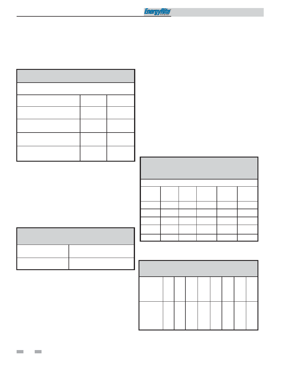
TABLE - 6A
INLET GAS PRESSURE
Measured at the inlet pressure tap located upstream of the
combination gas valve.
Model
Number
Natural
Gas
LPG
ER152 - ER202
Min. (Inches Water Column)
4.0
8.0
ER252 - ER302
Min. (Inches Water Column)
4.5
8.0
ER402
Min. (Inches Water Column)
5.0
8.0
ER152 - ER402
Max. (Inches Water Column)
14.0
14.0
Maximum inlet gas pressure must not exceed the value specified.
Minimum value listed is for the purposes of input adjustment.
MANIFOLD PRESSURE: Measured as a net pressure between
the pressure tap on the downstream side of the gas valve and the
chamber pressure. Connect one side of the manometer to the
chamber pressure, and the other to the outlet pressure tap. If
adjustment of the regulator pressure is required, see the
Manifold Adjustment Procedure section in the EnergyRite Service
Manual. Do not increase regulator pressure beyond specified
pressure settings.
TABLE - 6B
NET MANIFOLD PRESSURE
Model
Number
Natural and LP Gas
Regulator Setting
ER152 - ER402
(Inches Water Column)
1.8 (Nat.) 4.6 (LP)
Gas pressure test
1.
The pool heater must be disconnected from the gas
supply piping system during any pressure testing of that
system at a test pressure in excess of 1/2 PSIG (3.5 kPa).
2.
The pool heater must be isolated from the gas supply
piping system by closing its individual manual shutoff
valve during any pressure testing of the gas supply
piping system at test pressures equal to or less than
1/2 PSIG (3.5 kPa).
3.
The pool heater and its gas connection must be leak-
tested before placing the heater in operation.
Gas connection
Safe operation of the unit requires properly sized gas supply
piping. See the following data:
1.
Gas pipe size may be larger than heater connection.
2.
Installation of a union is highly recommended for ease of
service. Install union as close as possible to gas valve inlet.
3.
Install a manual main gas shutoff valve, outside of the
appliance gas connection and before the gas valve, when
local codes require.
4.
A trap (drip leg) must be provided in the inlet of the gas
connection to the unit.
5.
The combination gas valve has an integral vent limiting
device and does not require venting to atmosphere,
outside the building.
6.
Optional gas controls may require routing of bleeds and
vents to the atmosphere, outside the building when
required by local codes.
TABLE - 6C
LOW PRESSURE SINGLE UNIT INSTALLATIONS
SUGGESTED GAS PIPE SIZE
DISTANCE FROM METER
Model
Number
0 - 50' 51' - 100' 101' - 200' 201' - 300' 301' - 500'
ER152
3/4"
1"
1 1/4"
1 1/4"
1 1/2"
ER202
1"
1"
1 1/4"
1 1/2"
2"
ER252
1"
1 1/4"
1 1/2"
1 1/2"
2"
ER302
1 1/4"
1 1/4"
1 1/2"
1 1/2"
2"
ER402
1 1/4"
1 1/4"
1 1/2"
2"
2"
For each elbow or tee, add equivalent straight pipe to total
length from Table 6D.
TABLE - 6D
FITTINGS TO EQUIVALENT STRAIGHT PIPE
Diameter
Pipe
3/4"
1"
1 1/4" 1 1/2"
2"
3"
4"
5"
Equivalent
length of
Straight
Pipe
2'
2'
3'
4'
5'
10'
14'
20'