Sidewall venting – Lochinvar EnergyRite ER302 User Manual
Page 24
24
Installation & Operation Manual
5
Sidewall venting
The power sidewall venting system
Power sidewall venting with combustion air
from the equipment room
This venting system uses a power vent assembly which pulls the
flue products from the pool heater and exhausts out a sidewall.
The fan in the power vent cap generates a negative draft at the
unit. Combustion air is drawn from the equipment room (see
Combustion and Ventilation Air Requirements in the Determine
Pool Heater Location section). The outdoor vent cap must be
removed and the optional Sidewall Vent kit must be installed.
See the Installation of Optional Vent Kits section.
Figure 5-1_Power Sidewall Venting Installation
The sidewall fan is mounted in a vent cap which is installed on
an exterior wall. The sidewall fan and accessories are included in
a venting kit which must be furnished by the manufacturer in
accordance with CSA International requirements. This venting
kit includes a flue adapter, an air inlet cover, the sidewall fan/cap,
barometric damper, proving switch and all necessary relays to
interlock with the pool heater’s control system. A barometric
damper is required in the flue on Power Sidewall Venting
installations. A barometric damper is supplied with each Power
Sidewall Vent kit and MUST be installed in the flue of each unit.
The barometric damper must be adjusted to maintain a negative
draft between 0.02 to 0.08 inches water when the power sidewall
vent cap is operating. The barometric damper controls draft
and provides dilution air to the vent system to prevent
condensate formation. When a barometric damper is installed,
the equipment room must have adequate air to supply dilution
air to the barometric damper.
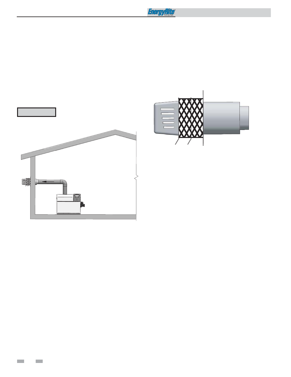
Figure 5-2_Power Sidewall Vent Cap
Sidewall vent termination
The power sidewall vent cap must be installed on an exterior
sidewall. The power sidewall vent cap and accessories are
included in a venting kit which must be furnished by the
manufacturer in accordance with CSA International
requirements. This venting kit includes a flue adapter, an air
inlet cover, the power sidewall cap, barometric damper, proving
switch, and all necessary relays to interlock with the heaters
control system.
The power sidewall vent cap MUST be interlocked with the pool
heater’s control system to start the fan on a call for heat and
prove fan operation before the pool heater fires. Terminal strip
connections are provided on the unit for easy connection of the
factory supplied vent kit and control package for the sidewall
vent fan. See the installation instructions provided with the vent
kit.
Sidewall vent pipe requirements
The connection from the vent to the power sidewall fan/cap
MUST be made with listed type “B” double-wall (or equivalent)
vent and accessories. There shall be no reduction in vent size
from the units flue outlet to the inlet of the sidewall vent fan.
Vent pipe material must be supplied by the installer.
Follow all requirements in the General Venting and Venting of
Flue Products sections for venting flue products to the outdoors.
See Combustion and Ventilation Air Requirements in the
Determine Pool Heater Location section to ensure that adequate
combustion and ventilation air is supplied to the equipment
room. All other general installation requirements must be
followed.
Length of flue pipe
The maximum total equivalent length of flue pipe connected to
the power sidewall cap cannot exceed 75 equivalent feet.
Subtract 5 feet for each elbow in the vent. Do not exceed the
limit for total equivalent vent pipe length.
CAUTION
The Power Sidewall Vent kit is to be used
for 120 VAC applications ONLY.