Water connections – Lochinvar EnergyRite ER302 User Manual
Page 34
34
Installation & Operation Manual
7
Water connections
This pool heater is equipped with an automatic, built-in bypass
located in the front header. This bypass is flow actuated to
maintain proper flow through the pool heater at flow rates of
less than 100 GPM. If the water flow rate to the pool heater
exceeds 100 GPM, an auxiliary bypass must be installed in the
piping to the pool heater. See the Auxiliary Bypass section for
piping and adjustment.
If the flow rate is unknown, ensuring the temperature rise across
the pool heater is between 10°F and 15°F will ensure the proper
flow rate (reference the Service Menu Descriptions - Delta T
section of the EnergyRite Service Manual).
TABLE - 7A
MINIMUM WATER FLOW REQUIREMENTS
Minimum water flow rates to ensure proper operation are
as follows:
Model
Minimum Flow
ER152
15 GPM
ER202
20 GPM
ER252
25 GPM
ER302
30 GPM
ER402
40 GPM
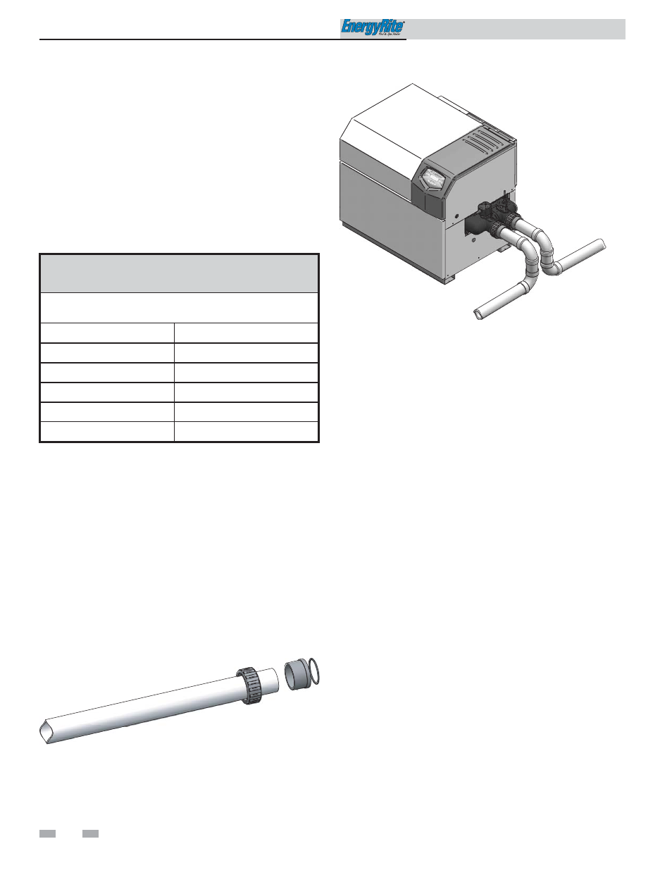
Figure 7-2_Typical Piping for Water Connections
Inlet and outlet connections
Connections can be made with 2" slip connections to both the
inlet and outlet connections. Included with the unit are two
CPVC union nuts (WTR2102), two CPVC tail pieces
(MSC2213), and two gaskets (GKT2071). Assemble the gasket
and tail piece with the union nut as shown in FIG. 7-1. Make
slip connections to the tail pieces using proper cement and
primer.
To use something other than PVC or CPVC pipe, connect the
tail pieces and gaskets with the union nuts as described above.
Connect six inches of PVC or CPVC pipe to the tail pieces as
described above. Connect a slip NPT adapter to the other end
of the six inch pipe. All other piping can be made there.
For ASME models please see the ASME Addendum section of
this manual for water connections.
A metallic pipe heat sink is not required on pool heater
installations. When the pool heater is used with a spa or therapy
pool, CPVC or metallic pipe is recommended. The filtration
pump must operate simultaneously when the heater is in service
to ensure that there is no damage to the piping connected
directly to the pool heater. A check valve should be installed in
the piping to the heater if there is the possibility of “back
siphoning” when the pump stops.
Auxiliary bypass
When water flow rates to the pool heater exceed 100 GPM, a
portion of this high water flow must be diverted with an
external bypass. High performance pumps can provide flows in
excess of 100 GPM. An auxiliary bypass as shown in FIG. 7-3
must be installed when the maximum flow is exceeded. The
bypass must have a valve installed between the connections to
the pool heater to allow a portion of the excess flow to be
diverted to the pool. The bypass allows the proper volume of
water to be supplied to the pool heater to prevent sweating and
condensate. The bypassed water prevents needless pressure
drop and reduction in flow rates.
Figure 7-1_Piping Connection Assembly