Asme addendum, Water connections – Lochinvar EnergyRite ER302 User Manual
Page 49
11
ASME addendum
(continued)
Installation & Operation Manual
49
Water connections
Inlet and outlet connections
Connection to the pool heater can be made with either 2"
threaded pipe or a slip connection with 1 1/2" or 2" pipe.
Two inch threaded pipe may be directly screwed into the
flanged header connections for both inlet and outlet piping.
Each pool heater is supplied with two sets of gaskets to allow
a flanged compression attachment of either 2" or 1 1/2"
copper pipe directly to the front header. Ensure that the
correct gasket is used to match the pipe diameter used.
Minimum pipe size for installation of the pool heater is
1 1/2" diameter.
NOTICE
The pool heater installation may require
a 3/4" drain pipe. Check with your local
code authorities. In these applications,
install a 3/4" threaded connection in the
piping, located immediately downstream
of the inlet/outlet connection on the
front header for system drainage.
A metallic pipe heat sink is not required on pool heater
installations. PVC, CPVC, or other high temperature plastic
piping may be used to pipe directly to the pool heater if
permitted by local codes. When the pool heater is used with
a spa or therapy pool, CPVC or metallic pipe is
recommended. A silicon type sealant with a high elasticity
must be used at flanged connections to prevent leakage.
This helps to compensate for the large differences in
expansion and contraction of the materials used in piping
and the flanged connections. The filtration pump must
operate simultaneously when the heater is in service to
ensure that there is no damage to PVC piping connected
directly to the pool heater. A check valve should be installed
in the piping to the heater if there is the possibility of “back
siphoning” when the pump stops.
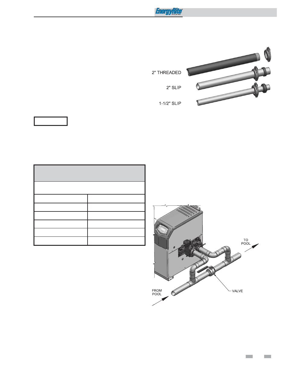
Figure 11-1_ Alternate Piping Connections
Auxiliary bypass
When water flow rates to the pool heater exceed 100 GPM, a
portion of this high water flow must be diverted with an external
bypass. High performance pumps can provide flows in excess of
100 GPM. An auxiliary bypass as shown in FIG. 11-2 must be
installed when the maximum flow is exceeded. The bypass must
have a valve installed between the connections to the pool heater
to allow a portion of the excess flow to be diverted to the pool.
The bypass allows the proper volume of water to be supplied to
the pool heater to prevent sweating and condensate. The
bypassed water prevents needless pressure drop and reduction in
flow rates.
Figure 11-2_ Auxiliary Bypass Piping
TABLE - 11A
MINIMUM WATER FLOW REQUIREMENTS
Minimum water flow rates to ensure proper operation
are as follows:
Model
Minimum Flow
ER152-A
15 GPM
ER202-A
20 GPM
ER252-A
25 GPM
ER302-A
30 GPM
ER402-A
40 GPM