Installation and service manual, Primary/secondary boiler piping – Lochinvar 399 User Manual
Page 35
Installation and
Service Manual
35
Example: The boiler inlet temperature is 160°F (71°C) and the
boiler outlet temperature is 180°F (82°C), this means that there
is a 20°F (11°C) temperature rise across the boiler.
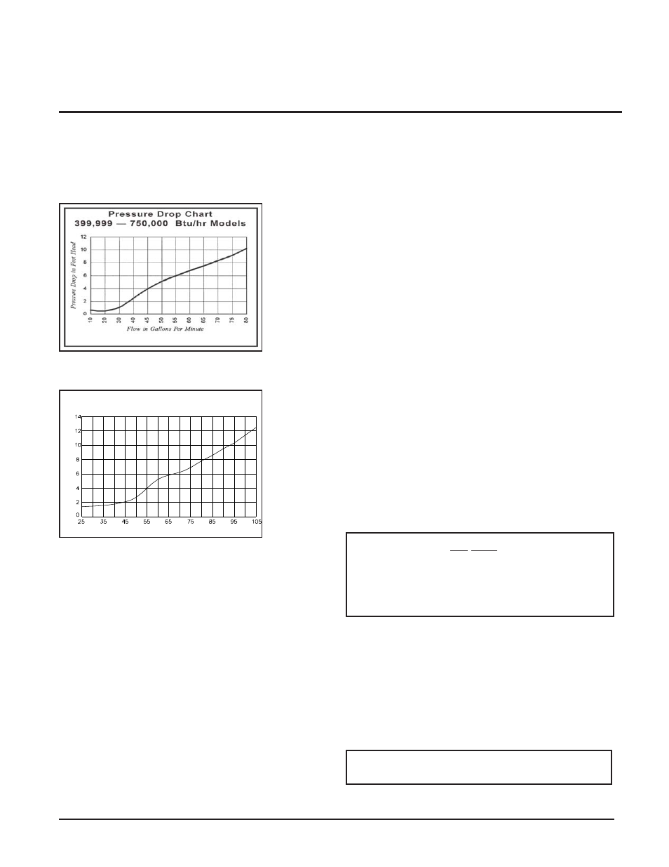
Heat Exchanger Pressure Drop Chart
FIG. 34 Pressure Drop Chart 399,999 - 750,000
FIG. 35 Pressure Drop Chart 990,000 - 2,070,000
Circulator Pump Specifications
1. Maximum operating pressure for pump must exceed
system operating pressure.
2. Maximum water temperature should not exceed nameplate
rating.
3. Cast iron circulators may be used for closed loop systems.
4. A properly sized expansion tank must be installed near the
boiler and on the suction side of the pump.
Circulator Pump Operation
(Heating Boilers Only)
The boiler pump should run continuously unless the boiler is
provided with the pump delay control system. External wire
leads are furnished with this option to allow the power supply
for the pump to be switched across the normally open contacts
of the relay, allowing the control relay to cycle the pump on
each call for heat. The field installed boiler pump using the
factory supplied pump control system must not exceed
10 AMPS at 120VAC. As shipped from the factory, the control
system is set to cycle the boiler pump on at each call for heat
before the burners fire and run the pump for a 30 second period
after the thermostat is satisfied. This will remove any residual
heat from the combustion chamber before turning the pump
off. See Wiring Diagram, page 64.
Pump Installation and Maintenance
For installation and maintenance information on the circulator
pump, refer to pump manufacturers instructions included in the
instruction package.
Primary/Secondary Boiler Piping
Boiler installations with a primary/secondary piping system as
shown in FIG. 36 are recommended. This type of system uses
a dedicated pump to supply flow to the boiler only. This
secondary pump is sized based on desired boiler flow rate,
boiler head loss and head loss in the secondary system piping
only. A properly-sized primary (system) pump provides
adequate flow to carry the heated boiler water to radiation, air
over coils, etc. The points of connection to the primary
(system) loop should be a maximum of 12" (or 4 pipe
diameters) apart to ensure connection at a point of zero
pressure drop in the primary system. Multiple boilers may also
be installed with a primary/secondary manifold system as
shown in FIG. 37. The multiple boilers are connected to the
manifold in reverse return to assist in balancing flow to
multiple boilers.
The installer must ensure that the boiler has adequate flow
without excessive temperature rise. Low system flow can
result in overheating of the boiler water which can cause short
burner on cycles, system noise and in extreme cases, a
knocking flash to steam. These conditions indicate the need to
increase boiler flow by installation of a larger circulator pump
or the installation of a system bypass. System noise may also
indicate an oversized boiler.
FLOW IN GALLONS PER MINUTE
PRESSURE DROP
IN FEET
HEAD
Pressure Drop Chart
990,000 - 2,070,000 Btu/hr Models
ƽ
CAUTION: DO NOT allow the flow in the
primary (system) loop to drop lower than the
flow in the secondary loop at any time during
boiler operation. Improper operation of the
boiler(s) and possible tripping of the high limits
and relief valves may occur.
ƽ
CAUTION: At no time should the system
pressure be less than 12 PSIG.