Installation and service manual, Gas manifold pressure adjustment – Lochinvar 399 User Manual
Page 31
Installation and
Service Manual
31
Check burner performance by cycling the system while you
observe burner response. Burners should ignite promptly.
Flame pattern should be stable, see Burner Flames, page 56.
Turn system off and allow burners to cool, then cycle burners
again to ensure proper ignition and flame characteristics.
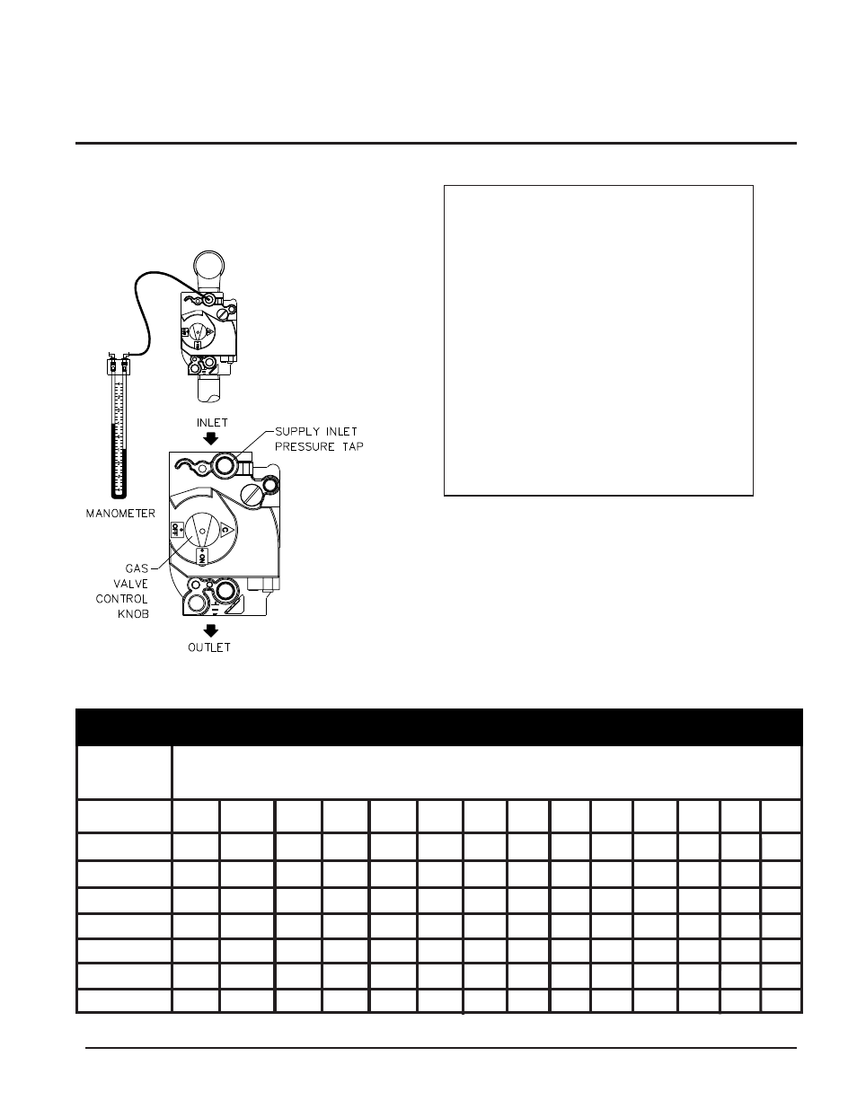
FIG. 30 Measuring Gas Supply Pressure at Combination
Gas Valve
Gas Manifold Pressure Adjustment
1. Loosen knurled knob that fastens the control panel access
door and pull out control panel.
2. Turn the power switch located in the lower left corner
behind the control panel access door to the “O” or “OFF”
position.
3. Remove the top front jacket access panels to access the gas
valves.
Nominal Iron
Length of Pipe In Straight Feet
Pipe Size,
(Inches)
10
20
30
40
50
60
70
80
90
100
125
150
175
200
TABLE - L
Multiple Unit Installations Gas Supply Pipe Sizing
3/4
"
369
256
205
174
155
141
128
121
113
106
95
86
79
74
1"
697
477
384
328
292
267
246
256
210
200
179
164
149
138
1 1/4
"
1,400
974
789
677
595
543
502
472
441
410
369
333
308
287
1 1/2
"
2,150
1,500
1,210
1,020
923
830
769
707
666
636
564
513
472
441
2"
4,100
2,820
2,260
1,950
1,720
1,560
1,440
1,330
1,250
1,180
1,100
974
871
820
2-1/2"
6,460
4,460
3,610
3,100
2,720
2,460
2,310
2,100
2,000
1,900
1,700
1,540 1,400
1,300
3"
11,200
7,900
6,400
5,400
4,870
4,410
4,000
3,800
3,540
3,300
3,000
2,720 2,500
2,340
4"
23,500
16,100
13,100
11,100
10,000
9,000
8,300
7,690
7,380
6,870
6,150
5,640 5,130
4,720
Maximum capacity of pipe in thousands of BTU’s per hour for gas pressures of 14 Inches Water Column (0.5 PSIG) or less and a total system
pressure drop of 0.5 Inch Water Column (Based on NAT GAS, 1025 BTU’s per Cubic Foot of Gas and 0.60 Specific Gravity).
IMPORTANT: The gas valves are
referenced to the fan pressurized
chamber by a hose connected from the
vent of the gas valve regulator to the
chamber pressure tap located on the front
inside portion of the jacket. Reference the
drawings in this section for component
and connection points for pressure
measurement. The procedure for
connecting a manometer or magnehelic
must be followed to obtain actual net
manifold pressure for normal operation. A
manometer or magnehelic gauge legible
in 0.1" increments up to 10 inches w.c. is
required to check and adjust the manifold
pressure. The regulator cover screw on
the gas valve must be in place and tight at
all times for the unit to operate properly.