Installation, Continued – Lochinvar 399 User Manual
Page 22
Hydronic Heating Boilers and
Domestic Water Heaters
22
INSTALLATION
Continued
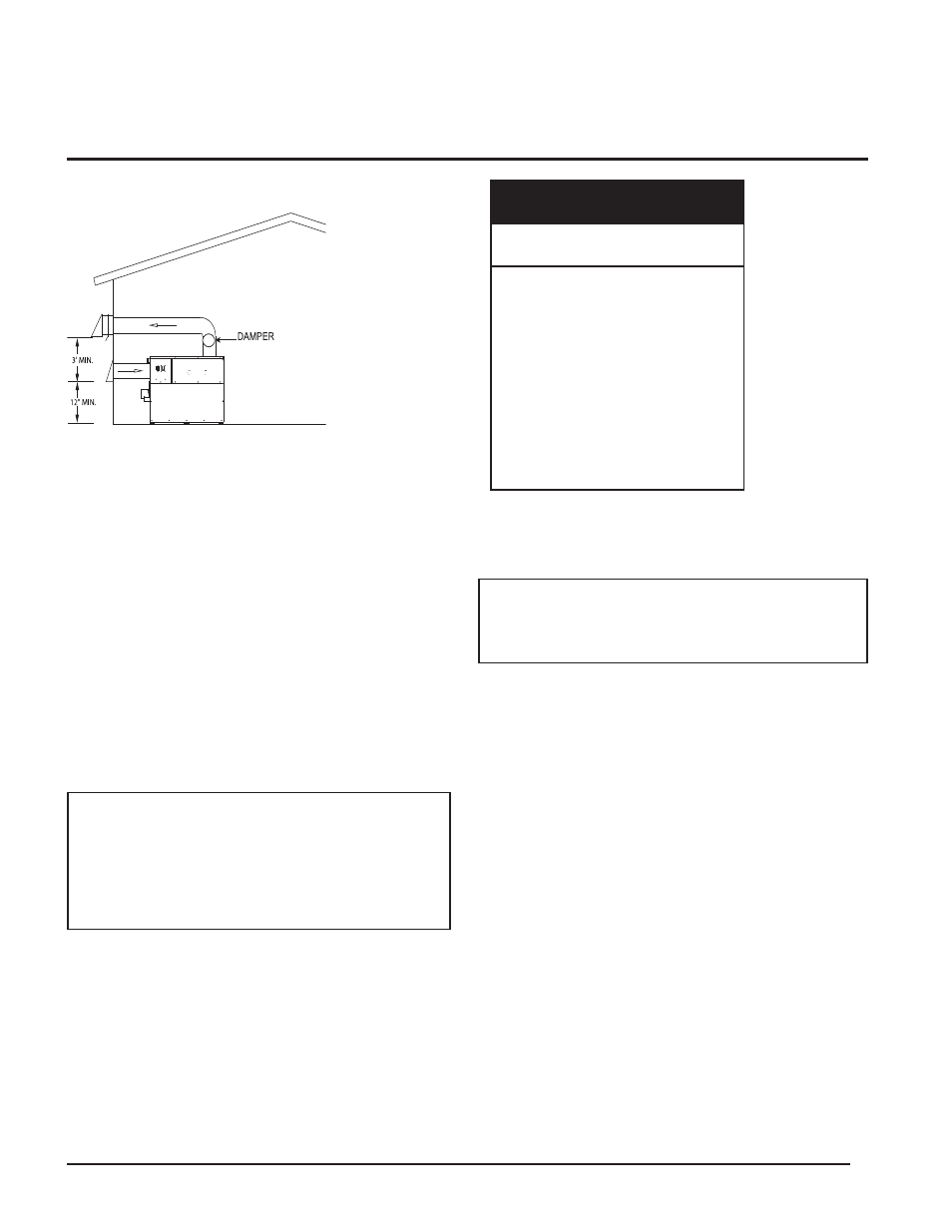
FIG. 23A Horizontal DirectAire Installation (Illustration
with Sidewall Venter and Sidewall Combustion Air)
Combustion air supplied from outdoors must be free of
contaminants (see Combustion and Ventilation Air, page 8).
Vent Kits
You must order the Horizontal DirectAire™ Vent Kit for
sidewall installation from the appliance manufacturer. See
TABLE–F for kit numbers. Each kit includes a sidewall
powered vent cap fan, proving switch, controls, combustion air
inlet cap to supply air to a single unit, the transition adapter to
attach the field supplied single wall air inlet pipe to the unit
and installation instructions. Purchase flue pipe and air inlet
pipe locally.
The sidewall air inlet cap supplied in the Horizontal
DirectAire™ Vent Kit is used to supply combustion air to a
single boiler. Combustion air supply pipes from multiple units
can not be combined into a single air inlet pipe and inlet point.
Venting of Flue Products
For venting flue products horizontally, follow all requirements
in the installation instructions for sidewall venting.
Termination point for the flue products must follow the
clearance requirements in Sidewall Venting Termination,
page 19.
For proper operation, a barometric damper is provided for
Horizontal DirectAire
TM
installations. The damper will help to
ensure a draft between negative 0.04 to 0.08 inches w.c.
TABLE–E
Input
Btu/hr
Kit*
399,999
HDK3031
500,000
HDK3031
650,000
HDK3032
750,000
HDK3032
990,000
HDK3026
1,260,000
HDK3027
1,440,000
HDK3027
1,800,000
HDK3028
2,070,000
HDK3028
*These kits include a sidewall venter assembly, vent termination, DV box
adapter, sidewall air inlet cap, and a barometric damper.
5. Direct Venting
This option uses sealed AL29-4C vent materials for the flue
outlet piping and separate combustion air inlet piping. This
system terminates both the flue and combustion air inlet in the
same pressure zone. The flue outlet and combustion air intake
may terminate at either a sidewall or the rooftop.
To use the optional Direct Vent system, you must install
specific vent kits and venting materials. The following is a
detailed explanation of Direct Vent installation requirements,
including the components used and vent kit part numbers.
Flue Outlet Piping
Venting Guidelines
If using this venting option, a sealed AL29-4C venting system
for flue products is required on all models of this appliance.
This venting system operates with a positive pressure in the
vent. The internal combustion air blowers generate this
positive pressure which operates the combustion process and
also exhausts the flue products from the building.
This vent system has specific vent material and installation
requirements. Only use listed sealed AL29-4C vent system
materials. Follow all installation requirements. See TABLE–B,
page 13 for proper pipe size for your unit. A list of sealed
AL29-4C flue pipe manufacturers is located on page 24.
Seal all vent joints and seams gas-tight.
ƽ WARNING: Only use the sidewall air inlet
cap recommended by the appliance
manufacturer. Using another sidewall air inlet
cap may result in operational problems and the
spillage of flue products. Spillage of flue
products can cause personal injury or death due
to carbon monoxide poisoning.
TABLE-F
Horizontal DirectAire™ Kits
IMPORTANT: Before installing venting system,
follow all venting clearances and requirements
found in the Venting, General Information
section, page 11.