Adjustment, Test equipment required for alignment, Repair jig (chassis) – Kenwood TK-270G User Manual
Page 33
TK-260G/270G
33
ADJUSTMENT
Test Equipment Required for Alignment
Test Equipment
Major Specifications
1.
Standard Signal Generator
Frequency Range
150 to 175MHz
(SSG)
Modulation
Frequency modulation and external modulation.
Output
-127dBm/0.1
µ
V to greater than -47dBm/1mV
2.
Power Meter
Input Impedance
50
Ω
.
Operation Frequency
150 to 175MHz or more.
Measurement Range
Vicinity of 10W
3.
Deviation Meter
Frequency Range
150 to 175MHz.
4.
Digital Volt Meter
Measuring Range
10mV to 10V DC
(DVM)
Input Impedance
High input impedance for minimum circuit loading.
5.
Oscilloscope
DC through 30MHz.
6.
High Sensitivity
Frequency Range
10Hz to 1000MHz.
Frequency Counter
Frequency Stability
0.2ppm or less.
7.
Ammeter
5A.
8.
AF Volt Meter
Frequency Range
50Hz to 10kHz.
(AF VTVM)
Voltage Range
1mV to 10V.
9.
Audio Generator (AG)
Frequency Range
50Hz to 5kHz or more.
Output
0 to 1V.
10.
Distortion Meter
Capability
3% or less at 1kHz.
Input Level
50mV to 10Vrms.
11.
Spectrum Analyzer
Measuring Range
DC to 1GHz or more
12.
Tracking Generator
Center frequency
50kHz to 600MHz
Output Voltage
100mV or more
13.
8
Ω
Dummy Load
Approx. 8
Ω
, 3W.
14.
Regulated Power Supply
5V to 10V, approx. 3A
Useful if ammeter equipped.
■
The following parts are required for adjustment
1. Antenna connector adapter
The antenna connector of this radio uses an SMA terminal.
Use an antenna connector adapter [SMA(f) – BNC(f) or
SMA(f) – N(f)] for adjustment. (The adapter is not provided as
an option, so buy a commercially-available one.)
Note
When the antenna connector adapter touches the knob,
draw out the knob to mount the connector.
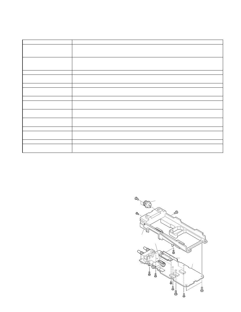
Repair Jig (Chassis)
1. Jig (chassis : Part No. A10-4009-03) for adjustment.
2. Use the jig as follows.
①
Place the TX-RX unit on the jig and fix it with thirteen
screws
∂
.
➁
Solder the antenna terminal of the TX-RX unit.
3. Supply power from an external power supply.
Relay terminal : + (7.5)
Jig (Chassis)
: -
Relay terminal
(+)
Power module
UNIT
JIG
Coaxial antenna connector
z
z
z
z
z
z
z
z
z