Circuit description, Control circuit, Optional board terminal – Kenwood TK-270G User Manual
Page 20
TK-260G/270G
20
CIRCUIT DESCRIPTION
Low battery warning
The red LED flashes during
transmission.
The red LED flashes and a
continuous beep sounds
while PTT is pressed.
Battery condition
The battery voltage is low but
the transceiver is still usable.
The battery voltage is low and
the transceiver is not able to
make calls.
6. Control Circuit
The control circuit consists of a microprocessor (IC13) and
its peripheral circuits. It controls the TX-RX unit and transfers
data to and from the display unit. IC13 mainly performs the
following:
(1) Switching between transmission and reception by the
PTT signal input.
(2) Reading system, group, frequency, and program data
from the memory circuit.
(3) Sending frequency program data to the PLL.
(4) Controlling squelch on/off by the DC voltage from the
squelch circuit.
(5) Controlling the audio mute circuit by the decode data input.
(6) Transmitting tone and encode data.
1) Frequency shift circuit
The microprocessor (IC13) operates at a clock of
9.8304MHz. This oscillator has a circuit that shifts the
frequency by BEAT SHIFT SW (Q31).
2) Memory circuit
Memory circuit consists of the CPU (IC13) and a flash
memory (IC12). A flash memory has a capacity of 2M bits
that contains the transceiver control program for the CPU
and data such as transceiver channels and operating
features.
This program can be easily written from an external device.
Data, such as DTMF memorise and the operating status,
are programmed into the EEPROM (IC10).
●
Flash Memory
Note : The flash memory holds data such as written with the
FPU (KPG-56D), and firmware program (User mode, Test
mode, Tuning mode, etc.). This data must be rewritten when
replacing the flash memory.
●
EEPROM
Note : The EEPROM stores tuning data (Deviation, Squelch,
etc.).
Realign the transceiver after replacing the EEPROM.
Fig. 9 Memory circuit
IC13
IC12
CPU
IC10
EEPROM
FLASH
3) Low battery warning
The battery voltage is monitored by the microprocessor
(IC13). When the battery voltage falls below the voltage set by
the Low Battery Warning adjustment, the LED flashes red to
notify the operator that it is time to replace the battery. If the
battery voltage falls even more (approx. 5.8V), a beep sounds
and transmission is stopped.
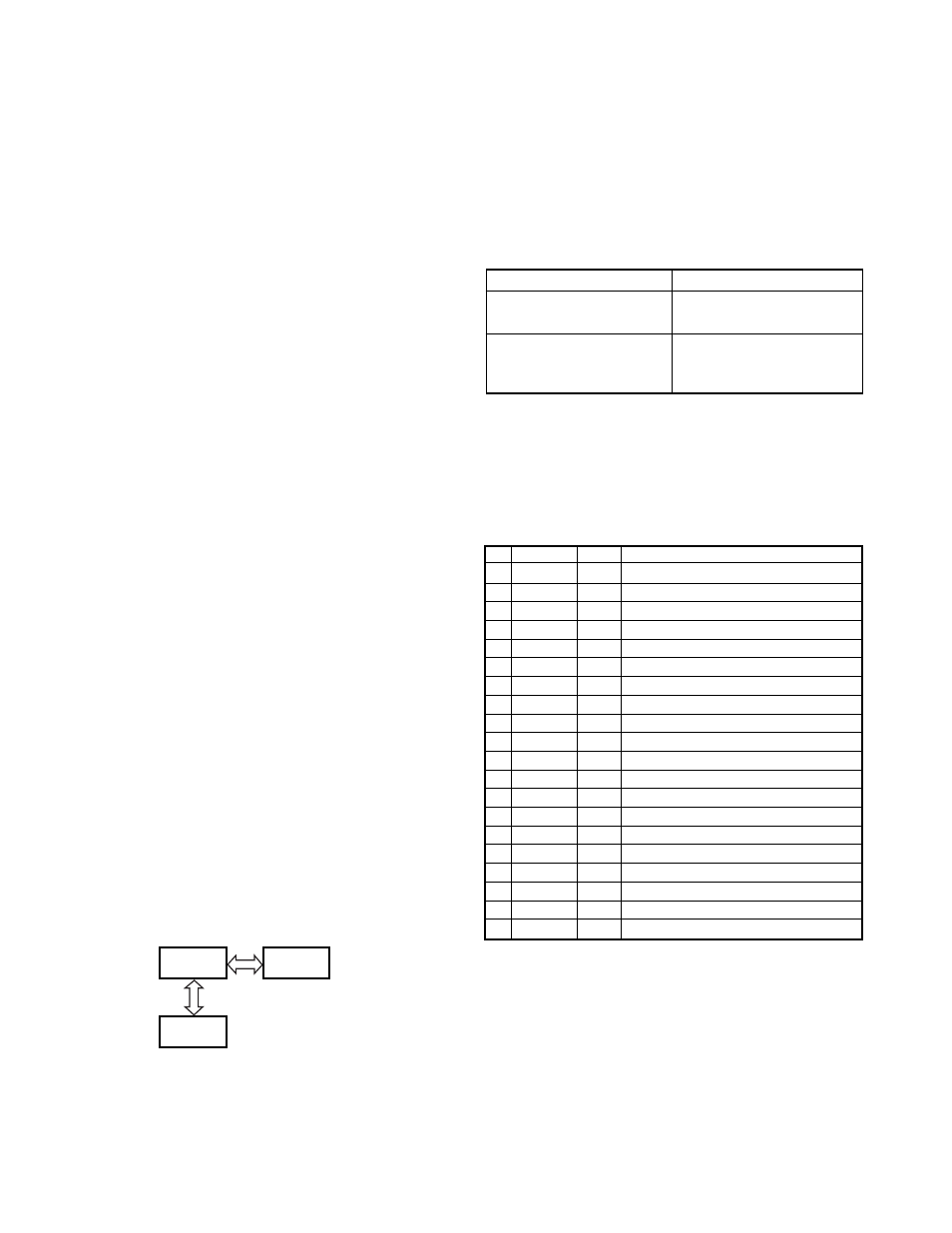
7. Optional Board Terminal
Terminals for mounting the option board are provided at
the bottom edge of the TX-RX unit. The table below shows the
correspondence between the board and terminals.
Optional Board Terminal Function (CN5)
Pin
Name
I/O
Function
1
GND
-
GND
2
SB
O
Power output after power switch
3
AUX3
I/O
Board control
4
TXAFI
I
Modulation output from board
5
AUX2
I/O
Board control
6
AUX6
O
Board control
7
AUX1
I
Board control
8
AUX5
O
Board control
9
AUX4
O
Board control
10 TXAFO
O
Modulation input to board
11 5C
O
5V
12 RXAFO
O
Received signal input to board
13 NC
-
NC
14 RXAFI
I
Received signal output from board
15 NC
-
NC
16 ALTTONE
I
ALART TONE output form board
17 NC
-
NC
18 NC
-
NC
19 NC
-
NC
20 GND
-
GND