1–3: mod.2 (filter1 modulation2), 1–3: mod.2 – KORG TRITON Le Electric Keyboard User Manual
Page 22
PROG
1.1
2.1
2.2
3.1
4.1
4.2
5.1
5.2
5.3
6.1
7.1
7.2
PROG
1.1
2.1
2.2
3.1
4.1
4.2
5.1
5.2
5.3
6.1
7.1
7.2
15
Int. to B (KBDTrk Int. to B)
[–99...+99]
Specifies the depth and direction of the effect on filter 1B
produced by keyboard tracking. (☞“Int. to A (KBDTrk Int.
to A)”)
4.1–2b: Filter EG
Int. to A (Intensity to A)
[–99…+99]
Specifies the depth and direction of the effect that the time-
varying changes created by the filter 1 EG will have on the
filter 1A cutoff frequency.
With positive (+) settings, the sound will become brighter
when the EG levels set by Filter 1 EG “L (Level)” and “T
(Time)” parameters (4.1–5a) are in the “+” area, and darker
when they are in the “–” area.
With negative (–) settings, the sound will become darker
when the EG levels set by Filter 1 EG “L (Level)” and “T
(Time)” parameters are in the “+” area, and brighter when
they are in the “–” area.
Int. to B (Intensity to B)
[–99…+99]
Specifies the depth and direction of the effect that the time-
varying changes created by the filter 1 EG will have on the
filter 1B cutoff frequency. (☞“Int. to A (Intensity to A)”)
Vel to A (Velocity to A)
[–99…+99]
This parameter specifies the depth and direction of the effect
that velocity will have on the time-varying changes created
by the filter 1 EG (as set by “Filter 1 EG” 4.1–5) to control the
filter 1A cutoff frequency.
With positive (+) values, playing more strongly will cause
the filter 1 EG to produce greater changes in cutoff fre-
quency. With negative (–) values, playing more strongly will
also cause the filter 1 EG to produce greater changes in cut-
off frequency, but with the polarity of the EG inverted.
Vel to B (Velocity to B)
[–99…+99]
This parameter specifies the depth and direction of the effect
that velocity will have on the time-varying changes created
by the filter 1 EG to control the filter 1B cutoff frequency.
(☞“Vel to A (Velocity to A)”)
■
4.1–2c: AMS, Into to A, Int to B
AMS (Filter EG AMS)
[Off, (EXT)]
Indicates the source that will control the depth and direction
of the effect that the time-varying changes produced by the
filter 1 EG will have on the cutoff frequency of filters 1A and
1B (☞p.212 “AMS List”).
Int. to A (AMS Int. to A)
[–99…+99]
Specifies the depth and direction of the effect that “AMS
(Filter EG AMS)” will have on filter 1A.
For details on how this will apply, refer to “Int. to A (Inten-
sity to A).”
Int. to B (AMS Int. to B)
[–99…+99]
Specifies the depth and direction of the effect that “AMS
(Filter EG AMS)” will have on filter 1B. (☞“Int. to A (Inten-
sity to A).”)
The sum of the settings for “Int. to A (B),” “Vel to A
(B),” and “Int. to A (B) (AMS Int. to A/B)” will deter-
mine the depth and direction of the effect produced by
the filter EG.
■
4.1–2d: UTILITY
☞ “Write Program” (1.1–1c), “Copy Oscillator,” “Swap
Oscillator” (2.1–1d)
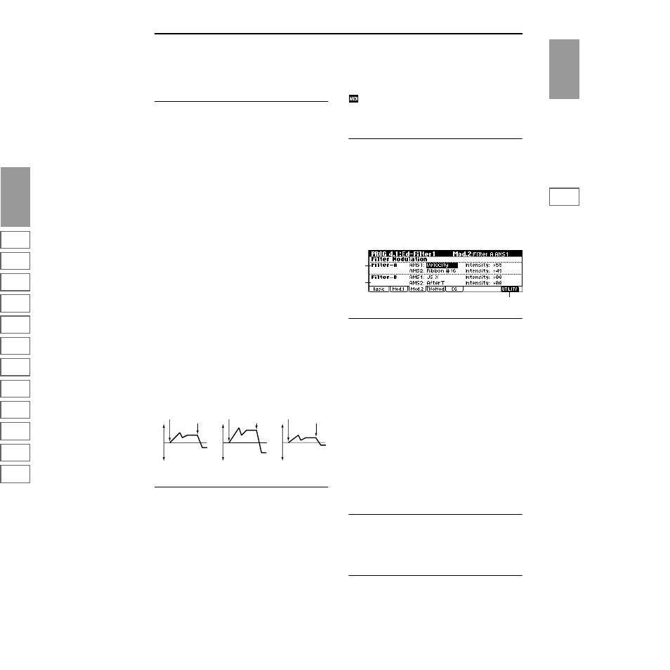
4.1–3: Mod.2
(Filter1 Modulation2)
Indicates settings for the controller that will modify the tone
by applying modulation to the filter 1 cutoff frequency “Fre-
quency (A/B Frequency).”
If “Type (Filter Type)” (4.1–1a) is Low Pass Resonance, the
filter B parameters will not be displayed.
4.1–3a: Filter-A Modulation
AMS1 (Filter A AMS1)
[Off, (PEG, AEG, EXT)]
Indicates the source that will control modulation of the filter
1A cutoff frequency (☞p.212 “AMS List”).
Intensity (A AMS1 Intensity)
[–99…+99]
Specifies the depth and direction of the effect that “AMS1
(Filter A AMS1)” will have.
When “AMS1 (Filter A AMS1)” is JS X, a positive (+) value
for this parameter will cause the cutoff frequency to rise
when the joystick is moved toward the right, and fall when
the joystick is moved toward the left. With a negative (–)
value
for this parameter, the opposite will occur.
This value is added to the setting of the Filter A “Frequency
(A Frequency)”(4.1–1b).
AMS2 (Filter A AMS2)
[Off, (PEG, AEG, EXT)]
Intensity (A AMS2 Intensity)
[–99…+99]
Selects “AMS2 (Filter A AMS2),” and specify the depth and
direction of the effect that the selected source will have
(☞“AMS1,” “Intensity”).
■
4.1–3b: Filter-B Modulation
This will be displayed when “Type (Filter Type)” (4.1–1a) is
Low Pass & High Pass
.
Two alternate modulation sources can be used to modulate
the cutoff frequency of filter 1B (☞“Filter-A Modulation”).
■
4.1–3c: UTILITY
☞ “Write Program” (1.1–1c), “Copy Oscillator,” “Swap
Oscillator” (2.1–1d)
Changes in cutoff frequency
Softly played
(The setting of Intensity to A (4.1–2b))
Strongly played
Setting to –
Strongly played
Setting to +
Note-on
Note-off
Note-on
Note-off
Note-on
Note-off
4.1–3a
4.1–3b
4.1–3c