2 drive, 3 operation, 1 paper lift plate mechanism – Konica Minolta 5430 DL 5440 DL 5450 User Manual
Page 111: 2 drive -74, 3 operation -74, 1 paper lift plate mechanism -74, 2 drive 13.3 operation
Media Feed Section (magicolor 5440 DL/5450)
Main Unit Theory of Operation
2-74
II Comp
osition
/O
p
eration
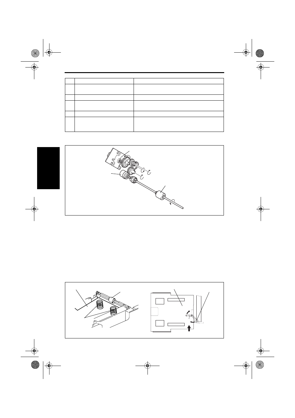
13.2 Drive
13.3 Operation
13.3.1
Paper Lift Plate mechanism
• The Paper Lift Plate is pressed down into the locked position (in which the paper is
loaded in position).
• Load a paper stack and then slide the tray into the machine. This causes the Lock
Release Lever to unlock the Paper Lift Plate.
• The Paper Lift Plate (paper stack) is pressed against the Feed Roller.
• The Paper Lift Plate (paper stack) is pressed upward by the springs at all times.
[6]
Paper Level Indicator Lever
• Indicates the level of the paper still available for use in
Tray 1
[7]
Paper Size Switch (S5)
• Detects the presence of the Tray1
[8]
Tray 1 Paper Feed Clutch (CL1)
• Transmits drive from the Intermediate Transport Motor
(M3) to the Tray 1 Feed Roller
[9]
Tray 1 Paper Empty Sensor (PC1)
• Detects the paper level in Tray 1
[10]
Paper Lift Plate
• Surface on which the paper stack is placed in Tray 1
• Maximum paper capacity
Plain paper: 500 sheets
Key
Name
Function/system
[1]
Intermediate Transport Motor (M3)
[3]
Tray 1 Feed Roller
[2]
Tray 1 Paper Feed Clutch (CL1)
4138to2058c0
[1]
[2]
[3]
4138to2606c0
4138to2605c0
Paper Lift Plate
Spring
Lock Release Lever
Feed Roller
Paper Lift Plate
5430DL_5440DL_5450_TO_PDF.book 74 ページ 2005年4月12日 火曜日 午後4時49分