Sub-Zero Sub-Zero User Manual
Page 37
37
F R A M E D C A B I N E T R Y –
B E A D E D I N S E T A P P L I C A T I O N
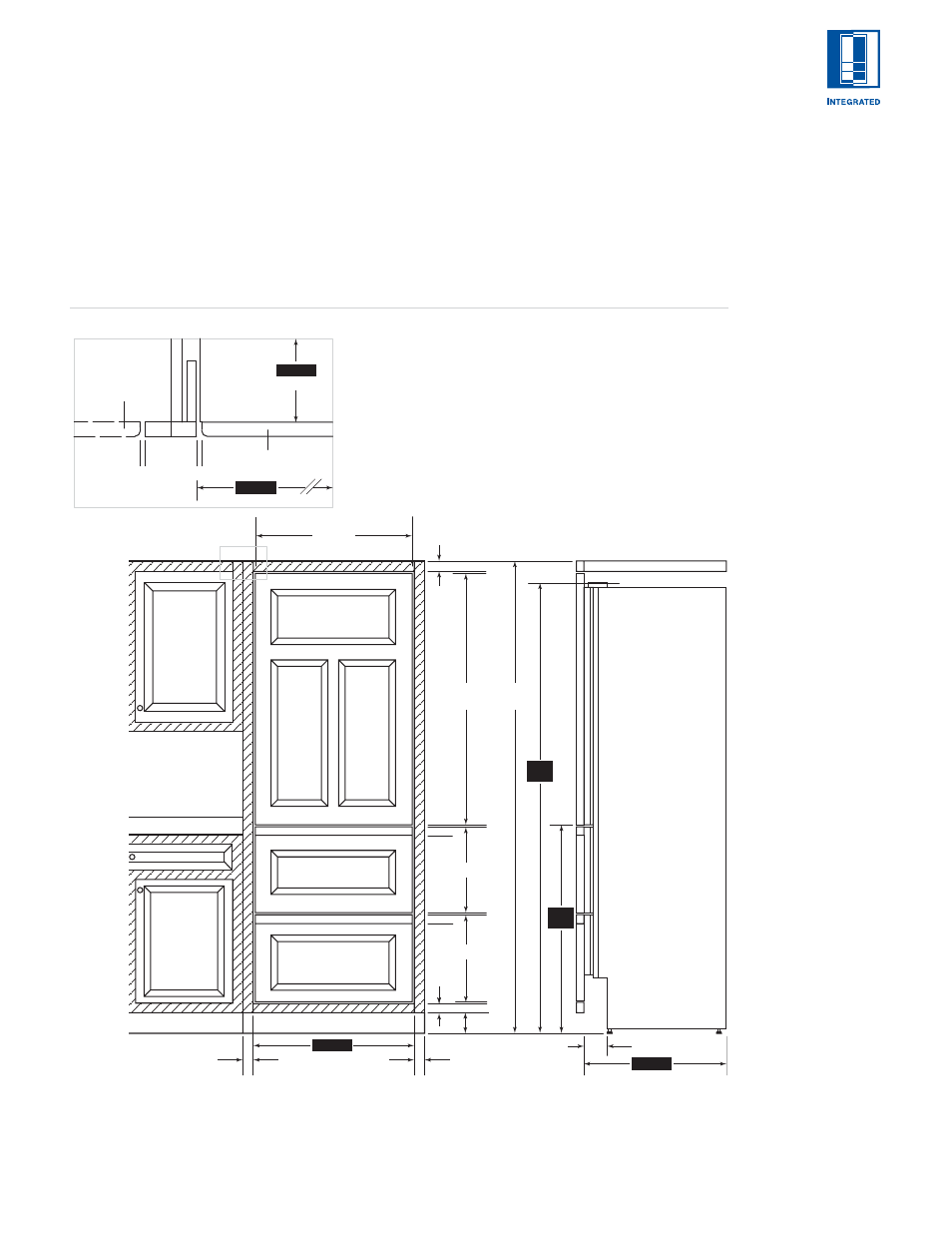
The illustration below shows a 686 mm wide
Integrated base or tall unit installed within a
framed cabinetry, beaded inset application.
Review, giving particular attention to the overall
panel specifications. Also refer to the full-scale
illustrations at the end of this section for
specifics on door openings.
A) ALL REVEALS ARE 3 mm
B) DRAWER RAILS ARE ATTACHED TO DRAWER FRONTS
C) BOTTOM RAIL MUST BE REMOVABLE
*DIMENSIONS MAY VARY
C
A
A
A
B
B
TOP VIEW
A
A
DOOR PANEL
CABINET DOOR
TO WALL
SUB-ZERO
UNIT
PANEL WIDTH
38
mm
38
mm
1216
mm
FRONT VIEW
SIDE VIEW
679 mm
345 mm
383 mm
2624
mm
38 mm
38 mm
102 mm*
102 mm
SHADED AREA
INDICATES STATIONARY
STYLES AND RAILS
610 mm
686 mm
2032
mm*
876
mm*
610 mm
686 mm
6 8 6 m m
W I D E M O D E L S
Installation of a
686 mm wide
Integrated base or
tall unit within
framed cabinetry.
*Dimensions may vary.
Dimensions are based
on a 3 mm reveal. A
reveal of up to 6 mm
is possible, but panel
dimensions need to be
adjusted accordingly.
I N S T A L L A T I O N
To install integrated
panels, see the
detailed procedures
outlined in the
Sub-Zero Integrated
Installation Guide.