1-3 connecting to a nonlinear editing system, 1-3 connecting to a nonlinear editing, System – Sony PDW-V1 User Manual
Page 32
Cha
p
te
r 3
Pre
par
at
ion
s
32
3-1 Connections and Settings
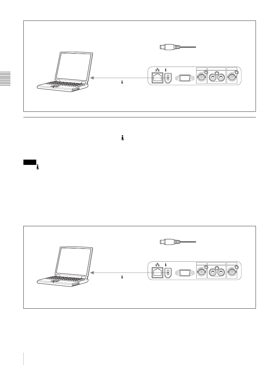
3-1-3 Connecting to a Nonlinear Editing System
You can send video/audio signals (AV/C data) from this
unit to a nonlinear editing system connected to the S400
(i.LINK) connector.
The following figure shows an example connection.
Notes
• The S400 (i.LINK) connector of this unit outputs
video/audio signals in DVCAM format. Data recorded in
MPEG IMX format is output after being converted into
DVCAM format.
• The nonlinear editing system to be used being connected
to this unit requires editing software (not supplied)
supporting DVCAM format.
• Make the following settings before transferring video/
audio signals (AV/C data) from this unit to a nonlinear
editing system.
Audio mode selection
Use extended menu item 831 “DV OUT AUDIO
MODE” to select either of the following.
2ch: 48 kHz/16 bits/2 channels (Factory default setting)
4ch: 32 kHz/12 bits/4 channels
Audio output channel selection
Select the audio output channels with extended menu
item 828 “SDI/DV AUDIO OUTPUT SELECT.”
For information about how to make extended menu item
settings, see 7-3-2 “Extended Menu Operatoins” on
page 75.
For the method of transferring video/audio signals (AV/C
data) to a nonlinear editing system, refer to the manual
provided with the editing software to be used.
VIDEO OUT
MONITOR
SDI OUT
AUDIO MONITOR OUT
L
R
S400
1
PDW-V1
S400 (i.LINK)
1
: i.LINK cable (not supplied)
To i.LINK (IEEE1394)
connector
Laptop computer
Make sure extended menu item 215 “PC REMOTE” is
set to “ena.”
VIDEO OUT
MONITOR
SDI OUT
AUDIO MONITOR OUT
L
R
S400
1
PDW-V1
S400 (i.LINK)
1
: i.LINK cable (not supplied)
To i.LINK(IEEE1394)
connector
Laptop computer
(With editing software supporting
DVCAM format installed)