State GPG/GPV-540A User Manual
Page 6
6
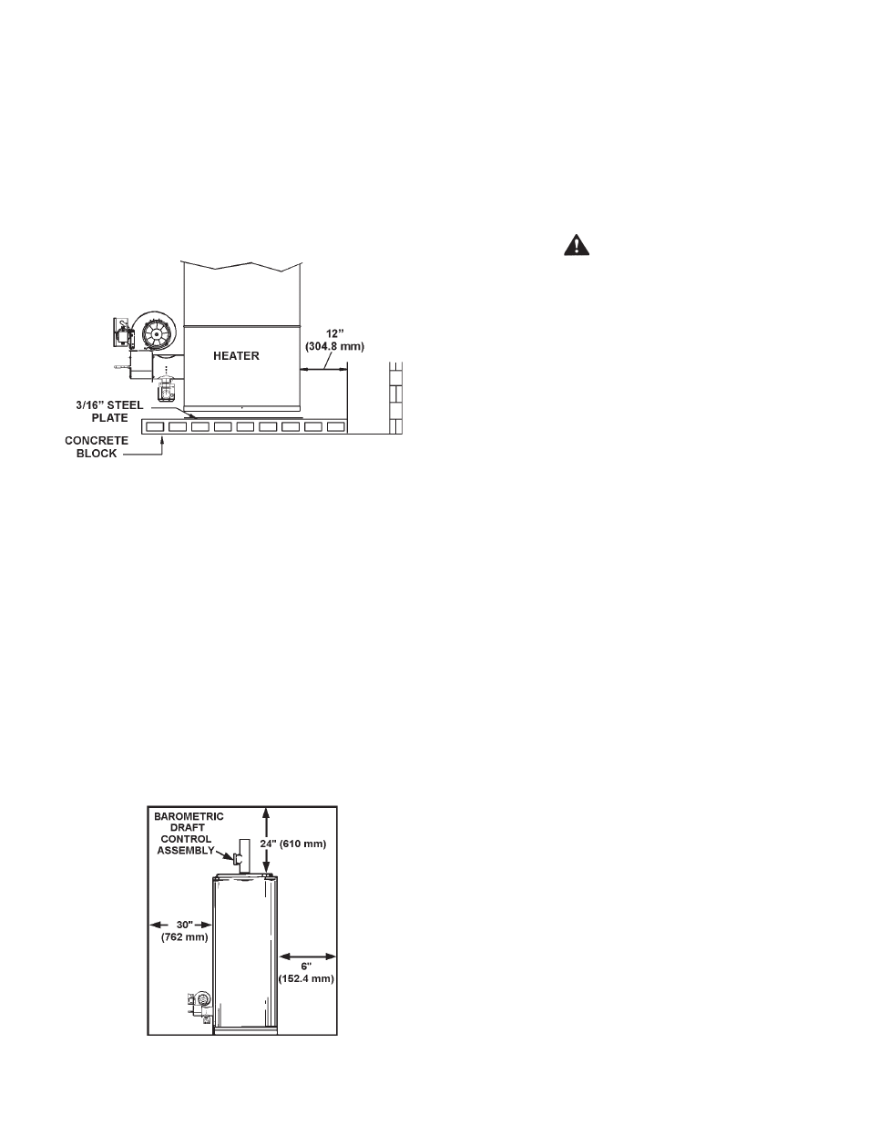
Units, which are to be installed on combustible flooring, must
be supported by a full layer of hollow concrete blocks, from
8” (203.2 mm) to 12” (304.8 mm) thick and extending
12” (304.8 mm) minimum beyond the heater in all directions.
The concrete blocks must provide an unbroken concrete surface
under the heater with the hollows running continuously and
horizontally. A 3/16-inch steel plate must cover the concrete
blocks, see Figure 2.
NOTE: If electrical conduits run under the floor of the proposed
heater location, insulate the floor as recommended above.
For appliances installation locations with elevations above 2000 feet
(609.6 m), refer to HIGH ALTITUDE INSTALLATIONS section.
PrOPEr iNSTALLATiON ON COMBUSTiBLE FLOOriNG
FiGUrE 2.
HArD wATEr
Where hard water conditions exist, water softening or the threshold
type of water treatment is recommended. This will protect the
dishwasher, Coffee urns, water heaters, water piping and other
equipment.
See MAINTENANCE section for details of tank cleanout
procedure.
CLEArANCES
These heaters are designed for installation on non-combustible
flooring in an alcove with clearances to combustible construction
of 6” (152.4 mm) from the sides and rear, 24” (610 mm) from the
top with a 6” (152.4 mm) minimum between vent pipe and ceiling.
Minimum clearance from flue pipe to combustible material is
6” (152.4 mm), see Figure 3.
PrOPEr iNSTALLATiON CLEArANCES
FiGUrE 3.
A clearance of 30” (762 mm) shall be maintained from serviceable
parts, such as power burners, relief valves flue baffles, thermostats
or drain valves.
Air rEQUirEMENTS
kEEP APPLiANCE ArEA CLEAr AND FrEE OF COMBUSTiBLE
MATEriALS, GASOLiNE AND OTHEr FLAMMABLE VAPOrS
AND LiQUiDS.
DO NOT OBSTrUCT THE FLOw OF COMBUSTiON Or
VENTiLATiNG Air.
wArNiNG
FOr SAFE OPErATiON PrOViDE ADEQUATE Air FOr
COMBUSTiON AND VENTiLATiON. AN iNSUFFiCiENT SUPPLy
OF Air wiLL CAUSE rECirCULATiON OF COMBUSTiON
PrODUCTS rESULTiNG iN Air CONTAMiNATiON THAT
MAy BE HAZArDOUS TO LiFE. SUCH A CONDiTiON OFTEN
wiLL rESULT iN A yELLOw, LUMiNOUS BUrNEr FLAME,
CAUSiNG CArBONiNG Or SOOTiNG OF THE COMBUSTiON
CHAMBEr, BUrNErS AND FLUE TUBES AND CrEATES A
riSk OF ASPHyXiATiON.
Where an exhaust fan is installed in the same room with a
heater, sufficient openings for air must be provided in the walls.
UNDErSiZED OPENiNGS wiLL CAUSE Air TO BE DrAwN
iNTO THE rOOM THrOUGH THE CHiMNEy, CAUSiNG POOr
COMBUSTiON. SOOTiNG MAy rESULT iN SEriOUS DAMAGE
TO THE HEATEr AND riSk OF FirE Or EXPLOSiON.
UNCONFiNED SPACE
In buildings of conventional frame, brick or stone construction,
unconfined spaces may provide adequate air for combustion and
ventilation.
If the unconfined space is within a building of tight construction,
(building using the following construction: weather stripping,
heavy insulation, caulking, vapor barrier, etc.), air for combustion
and ventilation must be obtained from outdoors or spaces freely
communicating with the outdoors. The installation instructions for
confined spaces in tightly constructed buildings must be followed
to ensure adequate air supply.
CONFiNED SPACE
When drawing combustion and dilution air from inside a
conventionally constructed building to a confined space, such a
space shall be provided with two permanent openings, ONE IN OR
WITHIN 12 INCHES (304.8 mm) OF THE ENCLOSURE TOP AND
ONE IN OR WITHIN 12 INCHES (304.8 mm) OF THE ENCLOSURE
BOTTOM. Each opening shall have a free area of at least one
square inch per 1000 Btuh of the total input of all appliances in the
enclosure, but not less than 100 square inches.
If the confined space is within a building of tight construction, air
for combustion and ventilation must be obtained from outdoors.
When directly communication with the outdoors through vertical
ducts, two permanent openings, located in the above manner,
shall be provided. Each opening shall have a free area of not
less than one square inch per 4000 Btuh of the total input of all
appliances in the enclosure.
VENTiNG
THE iNSTrUCTiONS iN THiS SECTiON ON VENTiNG MUST
BE FOLLOwED TO AVOiD CHOkED COMBUSTiON Or
rECirCULATiON OF FLUE GASES. SUCH CONDiTiONS CAUSE
SOOTiNG Or riSkS OF FirE AND ASPHyXiATiON.