Gas meter size – city gases only, Gas pressure regulation, Gas valves – State GPG/GPV-540A User Manual
Page 12
12
TABLE 9A
MAXiMUM CAPACiTy OF PiPE iN CUBiC FEET OF GAS PEr HOUr
(Based upon a Pressure Drop of 0.5 inch water Column
and 0.5 specific Gravity Gas and max. gas press. of .5 psig)
LENGTH
iN
Nominal iron Pipe Sizes, Millimeters
METErS 1/2” 3/4” 1” 1 1/4” 1 1/2” 2” 2 1/2”
3”
4”
3.0
51 105 199 410
615
1160 1845
3221
6735
6.1
35
73 142 278
428
805 1277
2255
4626
9.1
28
59 110 225
346
644 1031
1830
3748
12.2
24
50
94
193
290
556
878
1552
3192
15.2
21
44
83
170
264
492
776
1391
2840
18.3
19
40
76
155
237
445
703
1259
2577
21.3
18
37
70
143
220
410
659
1142
2372
24.4
17
35
64
135
202
381
600
1083
2196
27.4
16
32
60
126
190
357
571
1010
2108
30.5
15
30
57
117
182
337
542
952
1962
38.1
13
27
51
105
161
299
483
864
1757
45.7
12
25
47
95
146
278
439
776
1610
53.3
11
23
42
88
135
249
401
717
1464
61.0
10
21
40
82
126
234
375
688
1347
wArNiNG
THE HEATEr iS NOT iNTENDED FOr OPErATiON AT HiGHEr
THAN 14” (3.5 kPa) wATEr COLUMN (1/2 POUND PEr SQUArE
iNCH) SUPPLy GAS PrESSUrE. HiGHEr GAS PrESSUrES
rEQUirE SUPPLEMENTAL rEDUCiNG SErViCE rEGULATiON.
EXPOSUrE TO HiGHEr GAS SUPPLy PrESSUrE MAy
CAUSE DAMAGE TO THE GAS CONTrOLS wHiCH COULD
rESULT iN FirE Or EXPLOSiON. iF OVErPrESSUrE HAS
OCCUrrED SUCH AS THrOUGH iMPrOPEr TESTiNG OF
GAS LiNES Or EMErGENCy MALFUNCTiON OF THE SUPPLy
SySTEM, THE GAS VALVE MUST BE CHECkED FOr SAFE
OPErATiON. MAkE SUrE THAT THE OUTSiDE VENTS ON
THE SUPPLy rEGULATOrS AND THE SAFETy VENT VALVES
ArE PrOTECTED AGAiNST BLOCkAGE. THESE ArE PArTS
OF THE GAS SUPPLy SySTEM, NOT THE HEATEr. VENT
BLOCkAGE MAy OCCUr DUriNG iCE STOrMS.
iT iS iMPOrTANT TO GUArD AGAiNST GAS VALVE FOULiNG
FrOM CONTAMiNANTS iN THE GAS wAyS. SUCH FOULiNG
MAy CAUSE iMPrOPEr OPErATiON, FirE Or EXPLOSiON.
iF COPPEr SUPPLy LiNES ArE USED THEy MUST BE
iNTErNALLy TiNNED AND CErTiFiED FOr GAS SErViCE.
BEFORE ATTACHING THE GAS LINE, BE SURE THAT ALL GAS
PIPE IS CLEAN ON THE INSIDE.
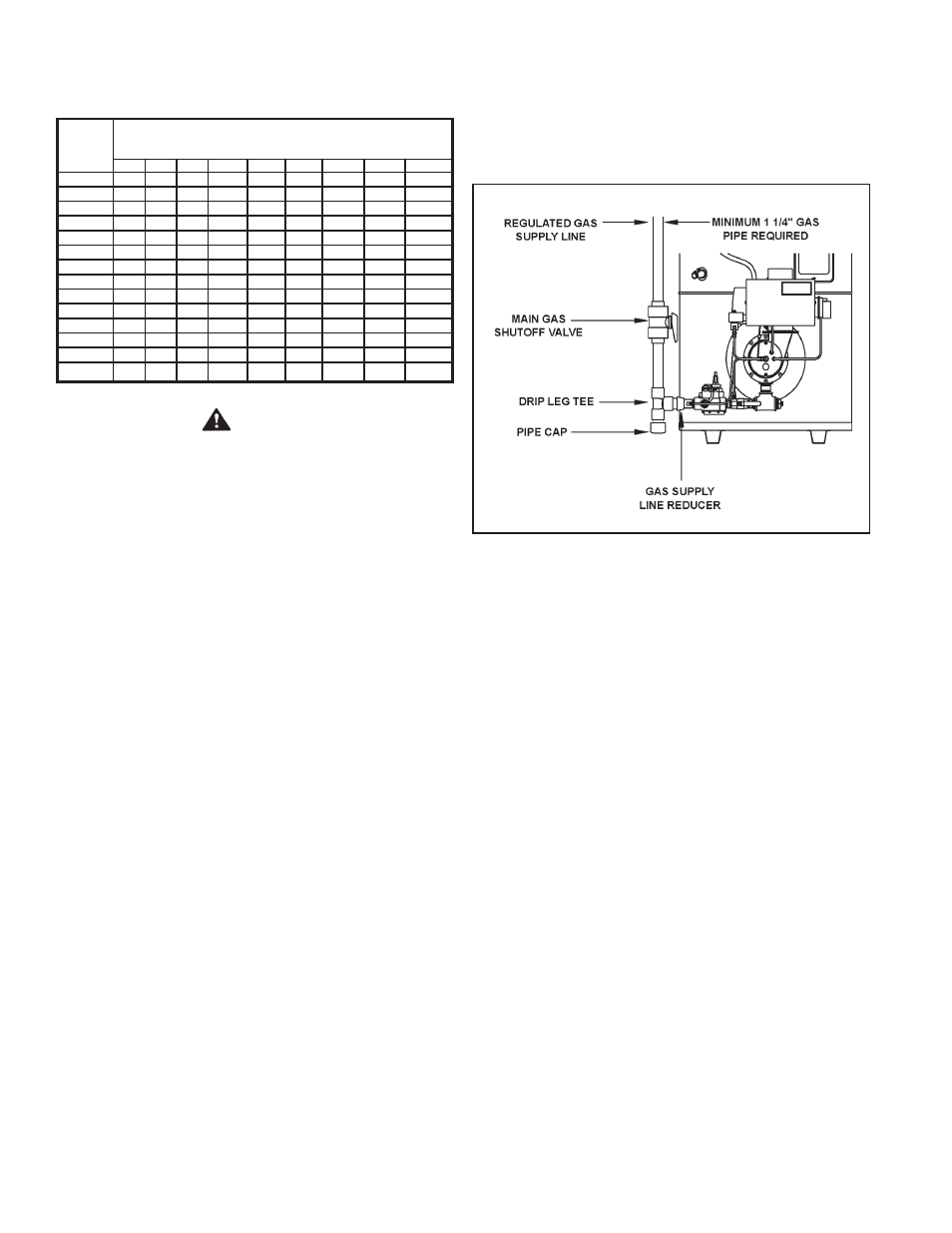
TO TrAP ANy DirT Or FOrEiGN MATEriAL iN THE GAS
SUPPLy LiNE, A DirT LEG (SOMETiMES CALLED A SEDiMENT
TrAP Or DriP LEG) MUST BE iNCOrPOrATED iN THE PiPiNG
(SEE FiG. 10) THE DirT LEG MUST BE rEADiLy ACCESSiBLE
AND NOT SUBJECT TO FrEEZiNG CONDiTiONS. INSTALL IN
ACCORDANCE WITH RECOMMENDATIONS OF SERVING GAS
SUPPLIERS. REFER TO THE NATIONAL FUEL GAS CODE.
To prevent damage, care must be taken not to apply too much
torque when attaching gas supply to gas valve inlet.
Apply joint compounds (pipe dope) sparingly and only to the
male threads of pipe joints. Do not apply compound to the first
two threads. Use compounds resistant to the action of liquefied
petroleum gases.
DiSCONNECT THE APPLiANCE AND iTS MANUAL GAS
SHUT-OFF VALVE FrOM THE GAS SUPPLy PiPiNG SySTEM
DUriNG ANy SUPPLy PrESSUrE TESTiNG EXCEEDiNG
1/2 PSiG. GAS SUPPLY LINE MUST BE CAPPED WHEN
DISCONNECTED FROM THE HEATER. FOR TEST
PRESSURES OF ½ PSIG OR LESS, THE APPLIANCE NEED
NOT BE DISCONNECTED, BUT MUST BE ISOLATED FROM
THE SUPPLY PRESSURE TEST BY CLOSING THE MANUAL
GAS SHUT-OFF VALVE.
GAS PiPiNG AND DirT LEG iNSTALLATiON
FiGUrE 9.
BEFOrE PLACiNG THE HEATEr iN OPErATiON, CHECk FOr
GAS LEAkAGE. USE SOAP AND WATER SOLUTION OR OTHER
MATERIAL ACCEPTABLE FOR THE PURPOSE IN LOCATING GAS
LEAKS.
DO NOT USE MATCHES, CANDLES, FLAME Or OTHEr
SOUrCES OF iGNiTiON FOr THiS PUrPOSE.
GAS METEr SiZE – CiTy GASES ONLy
Be sure that the gas meter has sufficient capacity to supply the
full rated gas input of the water heater as well as the requirements
of all other gas fired equipment supplied by the meter. If the gas
meter is too small, request the gas company to install a larger
meter having adequate capacity.
GAS PrESSUrE rEGULATiON
Main line gas pressure to the water heater should be between
8” w.c. (2 kPa) minimum (dynamic pressure or net pressure)
and 14” (3.5 kPa) maximum w.c. (static pressure). The inlet
gas pressure must not exceed the maximum value. A service
regulator is necessary if higher gas pressures are encountered,
see Table 10.
Due to pressure drop along gas supply line, to maintain
8” w.c. (2 kPa) minimum dynamic pressure, initial gas inlet pressure
must be set at higher than 8” w.c. (2 kPa). The gas regulator
must be properly sized to prevent unstable control or excessive
pressure drop.
GAS VALVES
Figure 10 shows the gas control valve that is supplied on
these heaters.