Rough-in dimensions, Foreword – State GPG/GPV-540A User Manual
Page 2
2
FOrEwOrD
The design of the GPG 540A through 740A models complies with
ANSI Z21.10.3/CSA 4.3 as an automatic circulating tank and an
automatic instantaneous type heater. The GPV 540A through
740A models are designed for sidewall venting and direct venting
applications and are certified under UL 795.
Detailed installation diagrams are found in this manual. These
diagrams will serve to provide the installer with a reference
for the materials and methods of piping necessary. It is highly
essential that all water, gas piping and wiring be installed as
shown on the diagrams.
Particular attention should be given to the installation of
thermometers at the locations indicated on the diagrams, as
these are necessary for checking the proper functioning of
the heater.
THE HEATER IS DESIGNED TO OPERATE ONLY ON
NATURAL GAS.
THESE HEATERS MUST NOT BE INSTALLED ON
COMBUSTIBLE FLOORS.
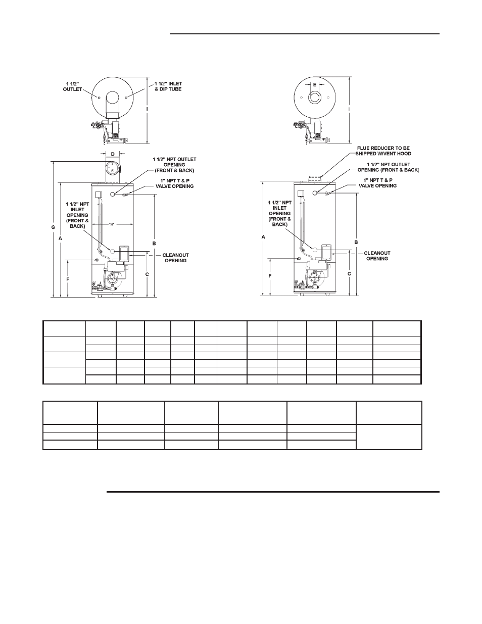
rOUGH-iN DiMENSiONS
STANDArD BArOMETriC DrAFT CONTrOL
GPG MODELS
HOriZONTAL & DirECT VENTiNG
GPV MODELS
ALL DiMENSiONS iN iNCHES (MiLLiMETErS)
Gas
Approx.
Models
A
B
C
D
E
F
G
H
i
Conn.
Ship. wt.
GPG/GPV
80 3/4
73
32 1/4
9
6
26 1/2
93
29 1/2
48 1/2
1*
950
540A
2,051
1,854
819
229
152
673
2,362
749
1,232
25.4
431 kg
GPG/GPV
80 3/4
73
32 1/4
9
8
26 1/2
93
29 1/2
48 1/2
1*
950
650A
2,051
1,854
819
229
203
673
2,362
749
1,232
25.4
431 kg
GPG/GPV
80 3/4
73
32 1/4
9
8
26 1/2
93
29 1/2
48 1/2
1*
950
740A
2,051
1,854
819
229
203
673
2,362
749
1,232
25.4
431 kg
*Minimum gas supply pipe is 1 1/4”, reference Table 7 for gas supply pipe size.
Storage
input rating
recovery rating
recovery rating
Current Draw
Capacity
BTU/Hr.
GPH
GPH
120V
Models
U.S. Gals. (Litres)
Nat.
100°F rise
140°F rise
60Hz 1 Phase
GPG/GPV-540A
85 (261)
540,000
523.6
374
GPG/GPV-650A
85 (261)
650,000
630
450
GPG/GPV-740A
85 (261)
740,000
718
512
Based on 80% thermal efficiency obtained in State engineering laboratories.
NOTE: To compensate for the effects of high altitude areas above 2000 feet, recovery ratings should be reduced approximately
4% for every 1000 feet above sea level.
6.0 Amps
MAXiMUM TOTAL 75 EQUiVALENT
FEET iNTAkE AND EXHAUST
ALLOwED.