Maintenance – Servis-Rhino 95HD User Manual
Page 36
INSTALLING SC SPOOL POSITIONER KIT (Item 2)
AND FLOAT POSITIONER KIT (Item 5)
1. Remove socket head cap screws and bonnet from
section.
2. Remove spool from section. Follow instructions in
Spool Seal Removal section except do not remove
seals.
3. Replace parts in spool positioner kit.
NOTE: Spool screw on end of spool is loctited in place. Do
not replace unless it is damaged. If spool screw must be
replaced, refer to Replacing Spool Ends Section.
4. Replace spool in section. Refer to instructions in
Spool Seal Installation section.
5. Replace bonnet and socket head cap screws.
REPLACING SPOOL ENDS - CENTER TWO
SECTIONS
Spool extensions (handle end) are installed at the factory
using Loctite 262. Spool screws (positioner end) are
installed at the factory using Loctite 242. Do not replace
them unless they are damaged. Use following procedure
to replace them.
1. Remove spool from section. Follow instructions in
Spool Seal Removal Section except do not remove
seals.
2. Clamp spool using vice grips on land section of spool
not machined for valve bore.
3. Unscrew damaged end.
NOTE: Heat may be applied to loosen Loctite.
4. Clean threads with Loctite Primer and install using
Loctite 262 for handle ends and Loctite 242 for
positioner ends.
5. Replace spool in section. Refer to instructions in
Spool Seal Installation section.
MAINTENANCE
MAINTENANCE
F3788-7-04
Maintenance Section 5-8
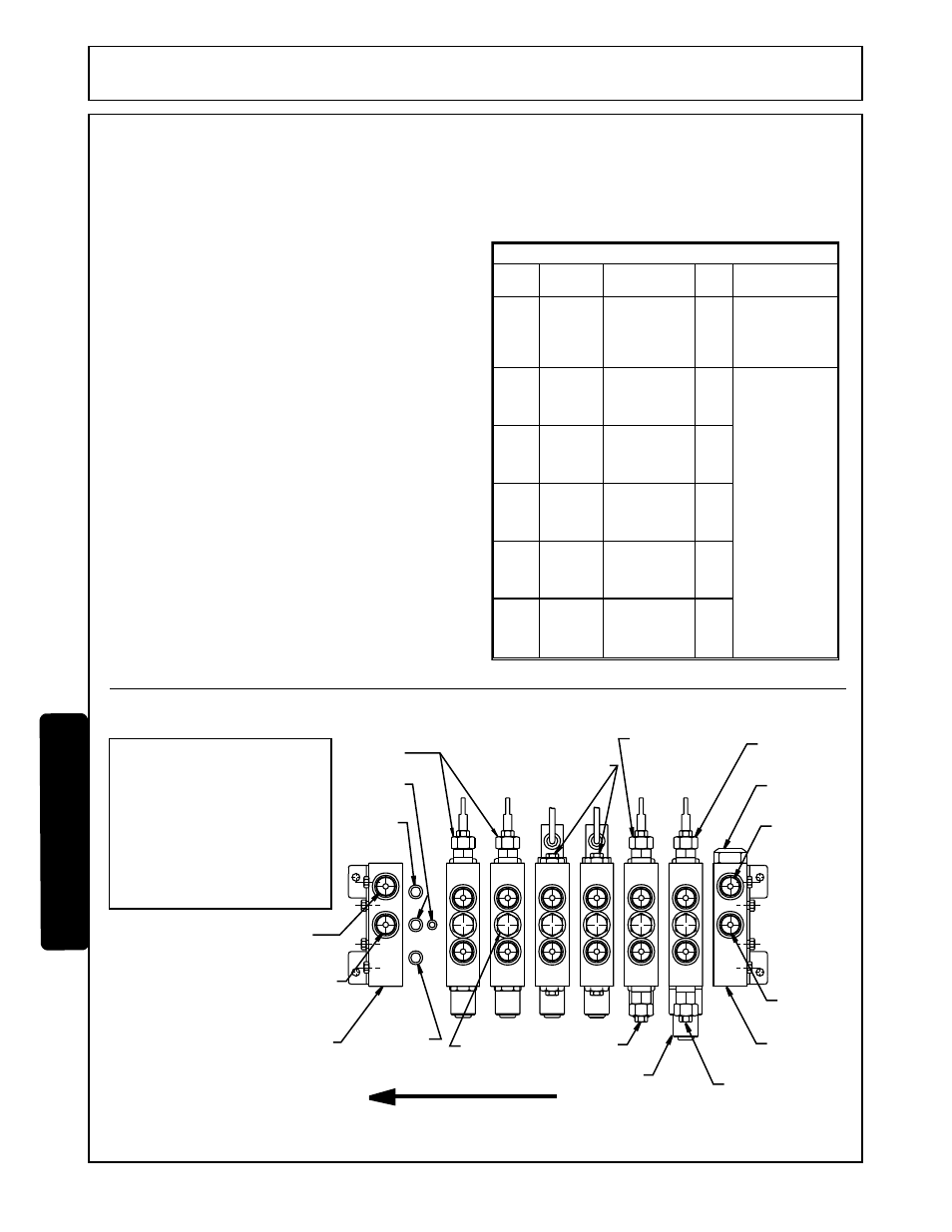
OUTLET PORT
3/4-16 O.R.
MACHINED TO
ACCEPT POWER
BEYOND SLEEVE
OUTLET
SECTION
PORT RELIEF
2650 PSI
PRESSURE
O-RINGS
EXHAUST
O-RING
LOAD
CHECK
EXHAUST
O-RING
6B: ROD END DIPPERSTICK CYLINDER
6A: BASE END DIPPERSTICK CYLINDER
5B: ROD END BUCKET CYLINDER
5A: BASE END BUCKET CYLINDER
4B: BASE END RIGHT STABILIZER CYLINDER
4A: ROD END RIGHT STABILIZER CYLINDER
3B: BASE END LEFT STABILIZER CYLINDER
3A: ROD END LEFT STABILIZER CYLINDER
2B: ROD END LEFT SWING CYLINDER
2A: ROD END RIGHT SWING CYLINDER
1B: BASE END BOOM CYLINDER
1A: ROD END BOOM CYLINDER
FLOW DIRECTION
PORT RELIEF
W/ ANTI CAVITATION
2650 PSI
PILOT
OPERATED
LOCK VALVES
(TOP AND
BOTTOM)
PORT RELIEF
W/ ANTI CAVITATION
2650 PSI
FLOAT
SECTION
PORT RELIEF
3500 PSI
PORT RELIEF
2650 PSI
MAIN RELIEF
2500 PSI
OUTLET PORT
3/4-16 O.R.
INLET PORT
3/4-16 O.R.
INLET
SECTION
1A
6B
6A
5B
5A
4B
4A
3B
3A
2B
2A
1B
RELIEF VALVE CARTRIDGE TABLE
Relief
type
Location Function
PSI How to test
Main
Port
relief
Port
relief
Port
relief
Port
relief
2500
3500
2650
2650
2650
Inlet
section*
Section 1,
A port*
Section 1,
B port*
Section 2,
A & B
ports*
Section 5,
A port*
Protect all
functions of
backhoe
Protect
backhoe from
bucket digging
induced loads
Plug gauge
directly into
stabilizer work
section and
operate stabilizer
A porta-power
with an oil
pressure guage
is required.
Install porta-
power pressure
hose directly
into working port
of relief to be
checked.
Pressurize
porta-power and
observe
maximum
pressure
attained. Port
reliefs should
“crack” at or
down to 200 PSI
below specified
relief setting.
Protect
backhoe from
bucket digging
induced loads
Protect swing
cylinder circuit
from shock
loading
Protect
backhoe from
bucket digging
induced loads
Port
relief
2650
Section 6,
A port*
Protect
backhoe from
bucket digging
induced loads
© 2004 Alamo Group Inc.