Maintenance – Servis-Rhino 95HD User Manual
Page 34
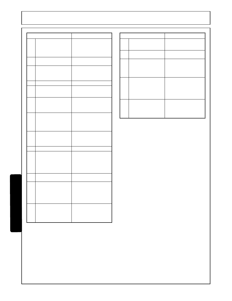
POSSIBLE CAUSE
CORRECTIVE ACTION
17
Oil leakage past spool
seal into spool cap.
If spool cap contains oil,
replace spool seal o-ring.
Check for restriction from
valve out port reservoir.
See Fig. 6, item 23.
18
Broken return springs. Return springs. See Fig.
6, items 2 & 5.
19
Bent spool.
Return for factory repair
or replace with new spool
section. See Fig. 6,
items 38, 39, 40.
20
Foreign particles.
Clean system and valve.
21
Misalignment of
control handle linkage.
Check linkage for binding
condition. Fig. 6, items 8,
11, 12.
22
Spool not moved to
full stroke.
Spool travel should be
265" either way or 53"
total. See Fig. 11, items
38, 39, 40.
23
Relief valve setting in
control valve too low
or defective.
Pressure should be 2500
PSI. Clean or overhaul
relief valve or replace
cartridge. See Fig. 11,
item 18.
24
Work port relief valve
in control valve stuck
open or
malfunctioning.
Clean relief or replace
cartridge. Do not disturb
pressure setting. See
Fig. 6, items 16, 17, 41.
25
Worn control valve.
Replace control valve.
26
Load check poppet in
control valve not
holding.
Clean check poppet(s)
carefully. Ensure free
movement and proper
seating or replace check
poppet(s). See Fig. 6,
item 26.
27
Damaged or worn
spool seals.
Replace spool end seals.
See Fig. 6, item 23.
28
Check ball in anti-
cavitation is stuck or
not seated properly.
Clean anti-cavitation
valve carefully. Assure
that checks move freely
and seat properly or
replace cartridge. See
Fig. 6, item 17.
29
Valve cap and center
return mechanism
binding.
Loosen screws holding
cap on valve. See Fig. 6,
items 2 & 5. Operate
valve spool and retighten
screws.
POSSIBLE CAUSE
CORRECTIVE ACTION
30
Restrictor in cylinder
ports are plugged.
Check restrictors for
debris and clean. See
Fig. 11, item 3.
31
Hoses plumbed incor-
rectly.
Check hose plumbing.
See Fig. 11.
32
Excessive hydraulic
pressure due to tractor
mechanical forces.
Do not move tractor
unless backhoe is up in
transport position and
backhoe can not contact
ground.
33
After valve has been
repaired, grease
lubrication on o-rings
between sections
cause spools to bind
due to valve distortion.
Disassemble and remove
lubricant from around o-
rings.
34
Valve studs are not
torqued to 15 ft. lbs.
Distortion causes
spool to bind or o-
rings to extrude.
Check studs for proper
torque.
This valve is a precision device and is not intended for
extensive field adjustment or repair. Field replacement
parts are limited to seal kits, cartridges, valve sections
and tie rod ends. Beyond replacement of these parts,
opening of check cavities and certain relief valve
cavities to examine for trapped dirt, or resetting main
relief valve with the use of a good pressure gauge,
valve should be returned for service.
Dirt and shreds of packing material are the usual causes
of valve malfunction. Be sure that oil supply is kept clean.
Use only factory supplied packings in cylinder repair.
Fittings and hoses must be clean before being removed.
Pages 5-7 & 5-8 explain proper valve repair procedure.
Pages 5-9, 6-16 &6-17 illustrate valve and lists repair
parts.
NOTE: Pay close attention to all caution warning notes so
valve will not have to be returned to manufacturer for
reconditioning.
Troubleshooting guide is designed to help qualified
individuals, with valve service training, correct minor
problems which may develop. If valve is under warranty
do not attempt disassembly for repairs. Contact your
authorized dealer.
MAINTENANCE
MAINTENANCE
F3788-7-04
Maintenance Section 5-6
© 2004 Alamo Group Inc.