3. system connections, Pcs-c1 camera unit to terminal camera cable, Tv monitor – Sony PCS-1P User Manual
Page 12: Supplied, Not supplied audio connecting cable, Pcs-p1 communication terminal
1-8
PCS-1/PCS-1P
1-3. System Connections
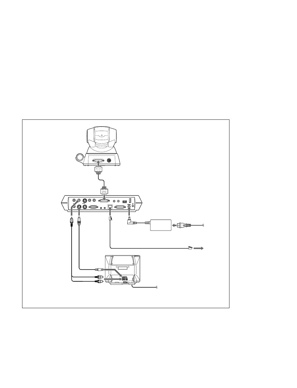
This section describes the typical system connections.
m
. Be sure to turn off all the equipment before making any connections.
. Do not connect/disconnect the camera cable with the power on. Doing so may damage the Camera Unit
or Communication Terminal.
. For safety, do not connect the 100BASE-TX/10BASE-T connector to a network that applies an excess
voltage via the 100BASE-TX/10BASE-T connector
1-3-1. When Used in LAN (100BASE-TX/10BASE-T)
DC 19.5V
AUDIO OUT
AUDIO IN
AUX1–
VIDEO IN
–AUX2
CAMERA UNIT
MIC
(PLUG IN POWER)
ISDN UNIT
WHITE
BOARD
(MIXED)
AUX
MAIN– MONITOR– SUB
VIDEO OUT
RGB OUT
DSB
IR OUT
100BASE-TX
10BASE-T
1
2
1
2
TERMINAL
VISCA OUT
PCS-C1 Camera Unit
to TERMINAL
Camera cable
*
to CAMERA UNIT
to DC19.5V
Power cord
*
to wall outlet
to 100BASE-TX/
10BADSE-T
PCS-AC195
AC adaptor
UTP cable (category 5, straight)
**
TV monitor
**
to a wall outlet
to LAN
to AUDIO
OUT
to VIDEO
OUT
MONITOR
MAIN
S-video
connecting
cable
*
to S-video
input
to audio input
*
supplied
**
not supplied
Audio
connecting
cable
*
PCS-P1
Communication
Terminal