Control examples using the gpi i/o connector – Sony BRS-200 User Manual
Page 121
121
Using the GPI I/O Connector
Cha
p
te
r 6
Co
nt
rol Using E
x
te
rnal De
vices
Setting example 2
When the Button1 (cross-point button 1) is lit in red, pin number 10 on the GPI
I/O connector short-circuits with GND.
It will be convenient to write down the functions assigned to each pin on the
chart below.
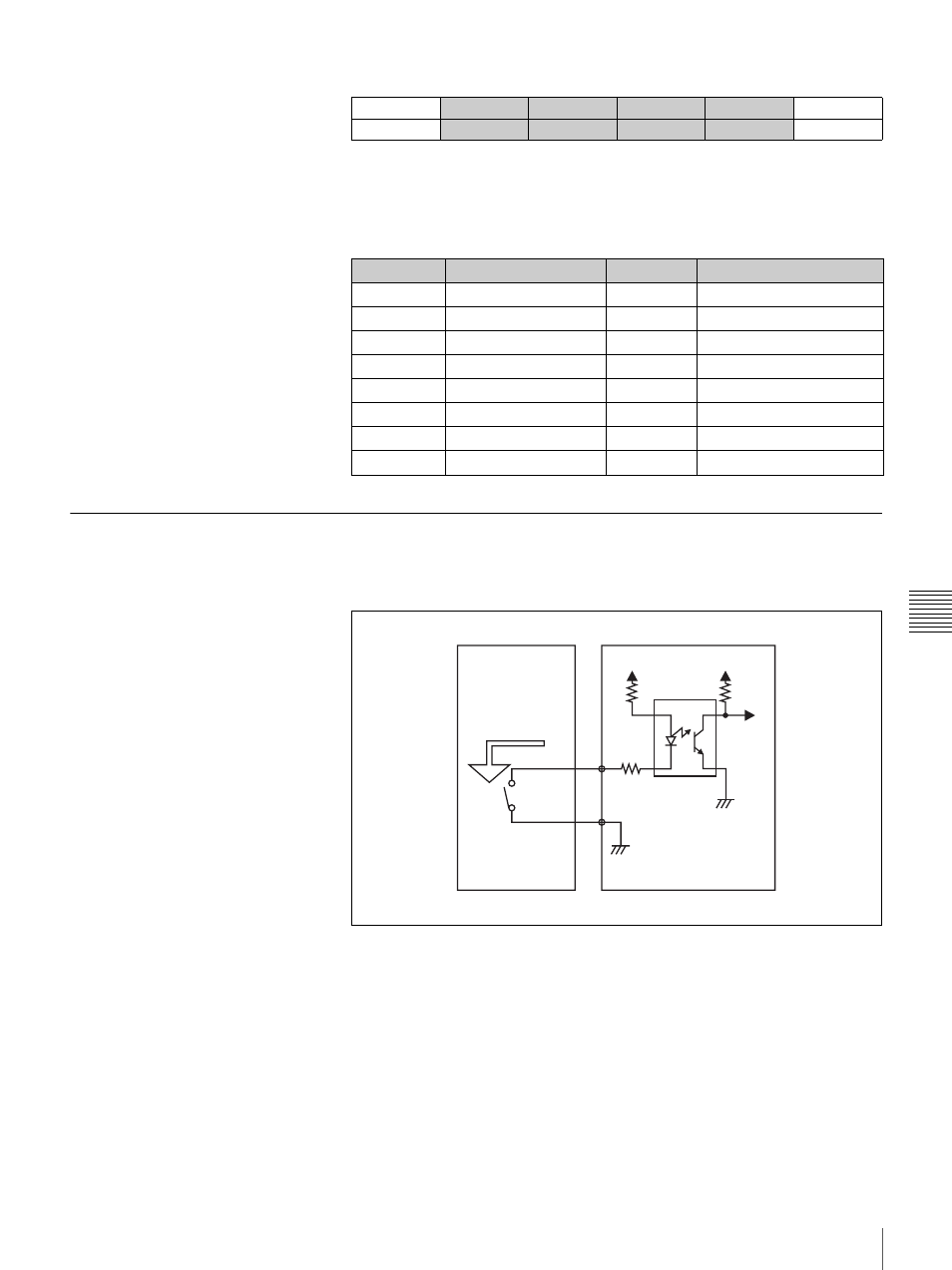
Control Examples Using the GPI I/O Connector
Input example 1: control example when an external switch is
connected
UTILITY
PIN NO
FUNCTION
COLOR
I/O DIR
1/3
GPI
10
Button1
Red
Output
961
Pin number
Function
Pin number Function
1
9
2
10
3
11
4
12
5
13
GND
6
14
GND
7
15
GND
8
5V
VCC
50 mA at
maximum
External device
Processor Unit of the
BRS-200
See also other documents in the category Sony Photo Accessories:
- SAL-85F14Z (2 pages)
- DSC-S780 (40 pages)
- DSC-S780 (102 pages)
- DSC-S780 (64 pages)
- CA-590P (22 pages)
- LCM-FD88 (2 pages)
- FCB-IX11AP (45 pages)
- HKCU-904 (74 pages)
- SAL-135F28 (2 pages)
- NEX-3C (82 pages)
- Camera Lens (2 pages)
- NEX-VG20 (3 pages)
- NEX-VG20 (117 pages)
- NEX-VG20 (155 pages)
- INFRARED REMOTE CONTROL RMT-DSLR1 (2 pages)
- EX48C (65 pages)
- MT4037S (2 pages)
- 370PK2 (160 pages)
- 35F14G (2 pages)
- AC-UP100 (2 pages)
- MV-100BAT (2 pages)
- APK-THA (2 pages)
- RIDE MOWER YTH 20 K 46 (2 pages)
- XDCU-50 (24 pages)
- SAL-14TC (2 pages)
- MSA-32A (2 pages)
- ERA-MS008 (2 pages)
- 500MM F8 REFLEX SAL500F80 (2 pages)
- SAL-24105 (2 pages)
- DT 18-55MM F3.5-5.6 SAM (2 pages)
- DSCT70 (40 pages)
- SAL-2875 (2 pages)
- 570WSPL (160 pages)
- MRW62E-S1 (2 pages)
- MRW62E-S1 (2 pages)
- MRW62E-S1 (1 page)
- MRW62E-S1 (2 pages)
- MSA512A-PINK (2 pages)
- 2-685-154-11(1) (2 pages)
- MagicGate MSGC-US10 (92 pages)
- ERA-210P1 (96 pages)
- SAL1118 (2 pages)
- FDA-SV1 (2 pages)
- LMP-E221 Replacement Lamp for VPL-E300-Series Projectors (2 pages)