Star Trac E-TBTe User Manual
Page 4
5
620-7921 Rev A
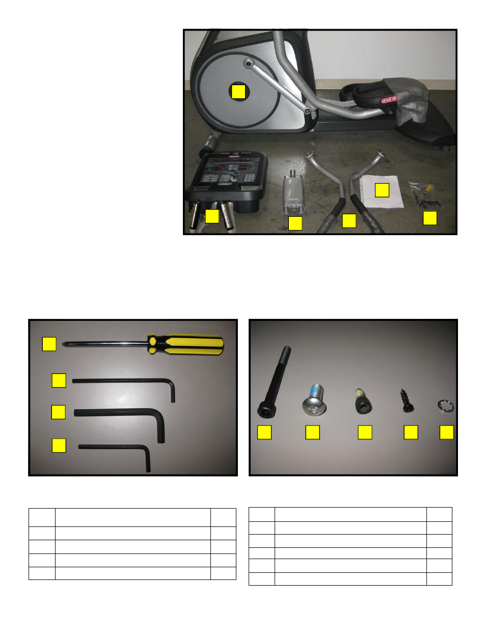
Step 5.
Remove remaining packaging ma-
terials and lay all components on
the floor.
Step 6.
Verify the following components
are included in the package:
1. TBT frame.
2. Display console assembly.
3. Upper neck.
4. Left and right upper body arms.
5. Owner’s manual, installation
manual and warranty registra-
tion card.
6. Hardware kit.
Step 7.
Verify the following tools are included in the kit:
Step 8.
Verify the following hardware is included in the kit:
Item Description
QTY
1
#2 Phillips screwdriver
1
2
3/16 Hex (Allen) key
1
4
5mm Hex (Allen) key
1
3
5/16” Hex (Allen) key
1
3
1
2
4
1
2
3
4
5
Item Description
QTY
1
6mm x 50mm socket head cap screw
4
2
5/16 - 18 x 3/4 button head screw
2
3
1/4 - 20 x 1/2 socket head screw
10
4
M4 x 0.7 x 19mm Philips head screw
6
5
Washer
4
1
2
3
4
5
6