Star Trac E-TBTe User Manual
Page 24
25
620-7921 Rev A
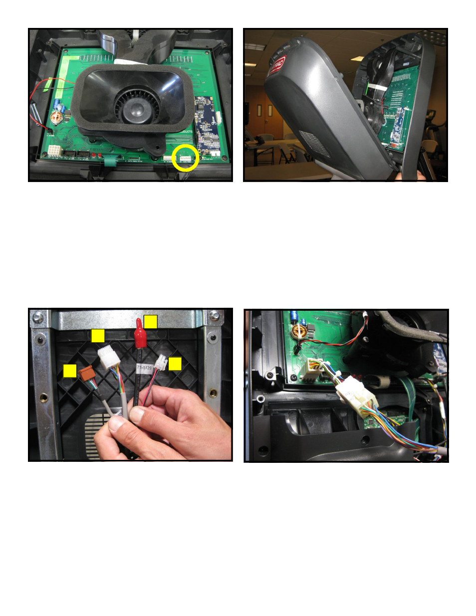
Step 26.
Take the front display plastics with the new cen-
ter console to the base unit. Hold the front dis-
play plastics at the top with one hand while con-
necting the cables and harnesses with the
other.
Step 27.
Identify the four cables coming out of the neck
and mounting bracket:
1. Heart rate cable
2. Main I/O cable
3. Coax cable
4. DC power cable
Note: The coax and DC power cables are part of the
PVS and embedded kits and should be tucked down
the neck for possible future use.
Step 28.
Plug-in the 12-pin main I/O cable from the neck
to the new 12 pin adaptor.
Step 25.
Connect the CSAFE power cable from the bot-
tom cover to J10 connector on the display
board.
1
2
3
4